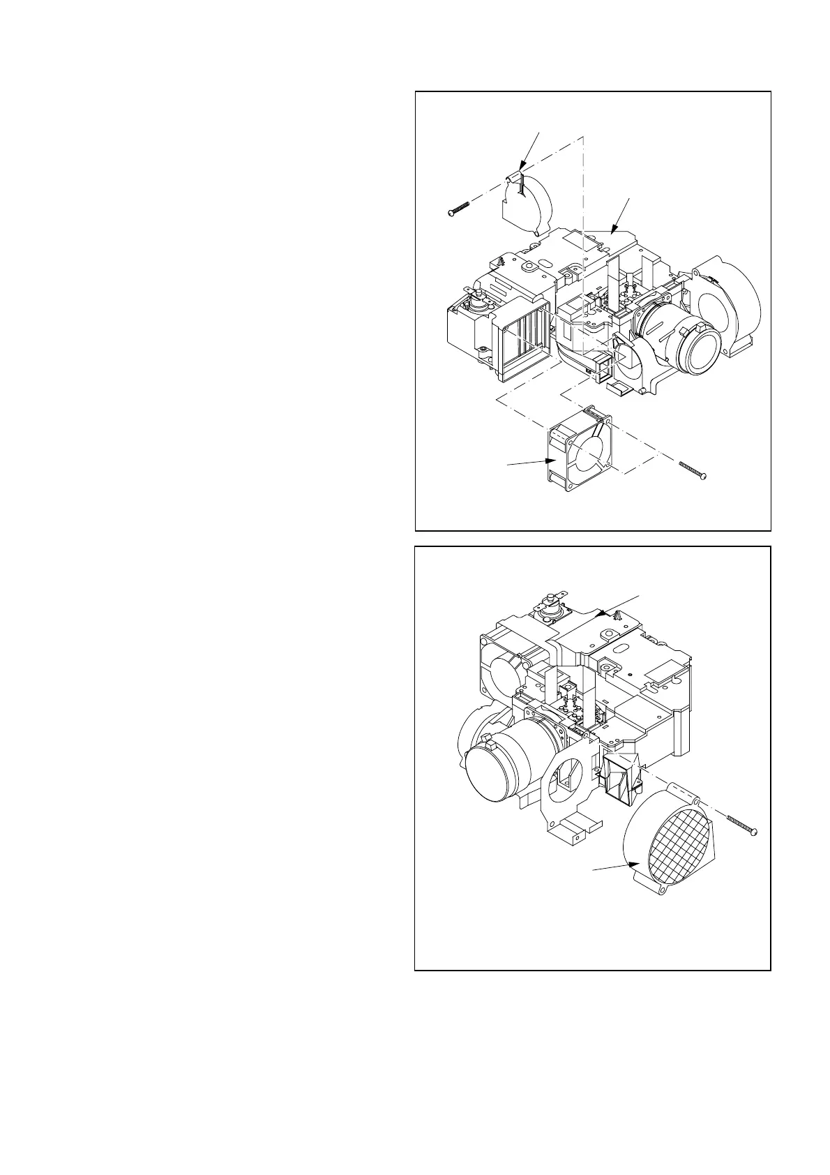
9. Removal of COOLING FAN UNIT ASSY
(PBS) and COOLING FAN UNIT ASSY
(EXHAUST)
1. Remove the Top Case Assy and the Terminal Board
following “1.Removal of TOP CASE ASSY and
SPEAKER”. (Fig. 3-1)
2. Remove the Terminal Assy (MAIN PCB ASSY, INLET
PCB ASSY, and TERMINAL PCB ASSY) following
“4.Removal of TERMINAL ASSY (MAIN PCB ASSY,
INLET PCB ASSY, and TERMINAL PCB ASSY) ”.
(Fig. 3-4)
3. Remove the Optical Unit following “8. Removal of
OPTICAL UNIT”. (Fig. 3-8)
4. Remove the (a) screw, and the Cooling Fan Unit Assy
(PBS) from the Optical Unit as shown in Fig. 3-9.
5. Remove the two (b) screws and the Cooling Fan Unit
Assy (Exhaust) from the Optical Unit as shown in Fig. 3-
9.
Fig. 3-10
10. Removal of COOLING FAN UNIT ASSY
(INTAKE)
1. Remove the Top Case Assy and the Terminal Board
following “1.Removal of TOP CASE ASSY and
SPEAKER”. (Fig. 3-1)
2. Remove the Terminal Assy (MAIN PCB ASSY, INLET
PCB ASSY, and TERMINAL PCB ASSY) following
“4.Removal of TERMINAL ASSY (MAIN PCB ASSY,
INLET PCB ASSY, and TERMINAL PCB ASSY) ”.
(Fig. 3-4)
3. Remove the Optical Unit following “8. Removal of
Optical Unit”. (Fig. 3-8)
4. Remove the (a) screw, and the Cooling Fan Unit Assy
(Intake) from the Optical Unit as shown in Fig. 3-10.
 Loading...