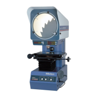
6.1.7 Connecting QM-Data 200
It is necessary to perform the QM-Data 200 setting when connecting it to the counter unit.
For information about setting up QM-Data 200, refer to it’s user’s manual.
(1) Connection
Connecting cable
(
12AAD192
)
QM-Data 200
Counter
unit
(2) QM-Data 200 setup
Select "SYSTEM" key of operation panel.
Measuring Instrument Setting--> Counter Type--> Profile Projector with RS Output
After the selection, the communication condition of QM-Data 200 becomes as follows.
Baud rate 9600bps Data bits 7bit
Parity Even Stop bits 1bit Flow control None
When QM-Data 200 starts, the counter display of projector fades away and LED of
inch/mm display at the counter blinks on and off. The switches on the projector
counter become ineffective.
NOTE
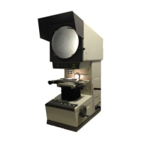
6.1.8 Data output (SPC)
While the projector may be used on a stand alone basis, it also has the capability of transmitting data
to external devices through the counter. Incorporating the projector into the M-SPC(Mitutoyo
Statistical Process Control) system permits measurements from the projector to be statistically
analyzed in order to create histograms and process control charts, etc. Data output from the counter
is initiated on the connected processor such as Digimatic Data-Processor. Measurement data
displayed on the counter will be transmitted.
If the projector is being used with a data processor, output data may not be consistent with the
displayed values when the counter is set to zero.
(1) OUTPUT connector specification
• Applicable SPC cable : P/N : 965013
• IN/OUT direction OUT : Counter → Connected device
Pin number Signal I/O direction Description
1 GND(Logic) Grounded
2
*1
DATA OUT Measured data
3
*1
CK OUT Clock for data transmission
4 N.C Not used
5
*2
REQ IN Request to send
6-9 N.C Not used
10 GND(Logic) Grounded
*1 Open collector : 5.25V, 10mA max
*2 C-MOS:Raised to Vcc(+5V)
6 - 10 No.99MBA043A