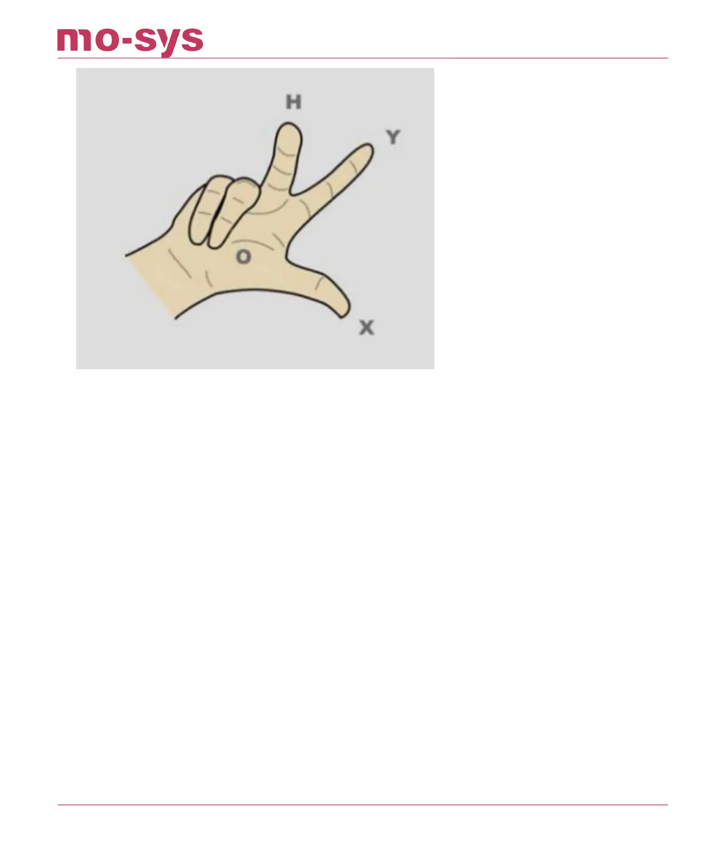
Discuss with the production team where talent or virtual graphics will be and make sure you
setup the axes the correct way. In general, the StarTracker Y axis will point towards the talent or
graphics location, and the StarTracker X axis will point to the right from the camera operator's
perspective. As shown in illustration below, the O-X axis is 90 degrees opposed to O-Y, with X to
the right of O-Y. Use masking tape set up and measure the O-X distance (note that the position
of 0 is for setup and reference. Its position can be easily relocated later).
0-X is roughly ½ of studio height.
The greater the O-X distance, the greater the accuracy of the StarTracker mapping to the studio.
Be as accurate as possible when measuring and marking the O and X positions.
8.1 Referencing vs Auto-Aligning
**IMPORTANT: Referencing is required when the sensor unit will not be mounted directly to a
camera (e.g. object tracker, mounted to a base of a crane or embedded in robotic head.)
If the sensor is mounted to the camera this section can be skipped and you can go
straight to Auto-Aligning (P.28)!
StarTracker Max Manual
2023 - 2024 © Mo-Sys Engineering Ltd. All rights reserved 28 of 70