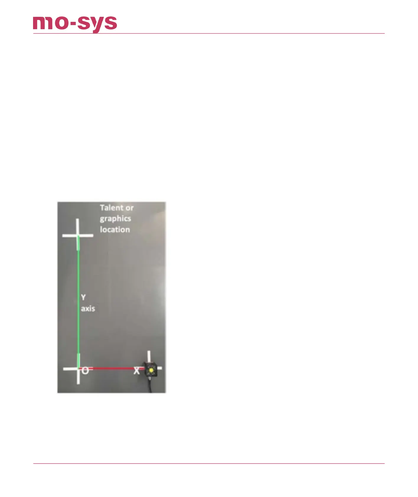
8.2 Placing Reference Points
Mark O, X and Y on the studio oor, using tape and a pen for reference points. Be certain to
measure accurately and use the same part of the sensor body each time you move. The O-X
distance will be used later to scale the map units to real-world units.
When dropping O (origin) and X it is critical to keep the pan value the same, to avoid pivotal
osets aecting measurements. It’s not necessary, when moving the sensor, to move in line
between points, or even remain on axis. The system will ignore movements between points and
automatically build the Y axis at a 90 deg angle to the O-X line. It is, however, important to
maintain the same height and ensure you are placing the sensor unit on the same side of the
axes line
Shown below the red and green lines on screen illustrate the direction of the x and y axes on the
map. By holding a nger over the ST sensor and aligning it with one of these lines, you will see
how the direction of the axes relate to the real world.
StarTracker Max Manual
2023 - 2024 © Mo-Sys Engineering Ltd. All rights reserved 29 of 70