Do you have a question about the Moeller MFD-CP4 and is the answer not in the manual?
Defines technical terms and components of the display/operator system.
Lists related manuals for easy basic units and where to download them.
Explains symbols and conventions used in the manual for clarity.
Specifies that installation and commissioning require trained electricians or familiar personnel.
Details correct installation and operational requirements for the MFD-CP4 unit.
Describes the system's capabilities, connectivity, and remote operation features.
Identifies and labels the components and buttons of the display/operator unit.
Explains the naming conventions and configurations for MFD-CP4 modules.
Details the functions of the display/operator unit buttons for navigation and operation.
Illustrates the navigation and display structure of the MFD-CP4's main menu.
Provides general instructions for installing the display/operator unit and power module.
Explains how to fit a protective membrane for special applications.
Describes the use and fitting of a protective cover for aggressive environments.
Details the process for front mounting the display/operator unit onto a panel.
Explains how to safely detach the display/operator unit from its mounting.
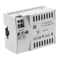
Illustrates the procedure for attaching the power supply/communication module.
Describes the steps to safely detach the power supply/communication module.
Details the types of terminals and tools used for connection.
Provides instructions and diagrams for connecting the DC power supply.
Explains how to connect the serial interface cable to the MFD-CP4 and basic units.
Outlines checks before powering on and initial safety precautions.
Describes the first-time setup process, including language selection.
Illustrates system configurations for direct serial connections.
Describes how the system functions within an EASY-NET network.
Details troubleshooting steps for connection interruptions or errors.
Explains how to manage graphic display modes and exit them.
Explains how to set the Station ID and baud rate for network communication.
Guides users on how to change the language displayed on the unit.
Describes how to adjust the brightness of the display.
Explains how to adjust the contrast of the display for better readability.
Detailed physical dimensions for display/operator units and protective accessories.
Comprehensive specifications including climatic, mechanical, EMC, and power supply details.
Information on required tools and suitable cable gauge sizes for terminals.
Guidelines for installing components, including LCD, LEDs, and operating buttons.
| Supply voltage | 24 VDC |
|---|---|
| Protection class | IP20 |
| Output voltage | 24 VDC |
| Manufacturer | Moeller |
| Protection | Short-circuit, overload |