11
www.monitorproducts.com
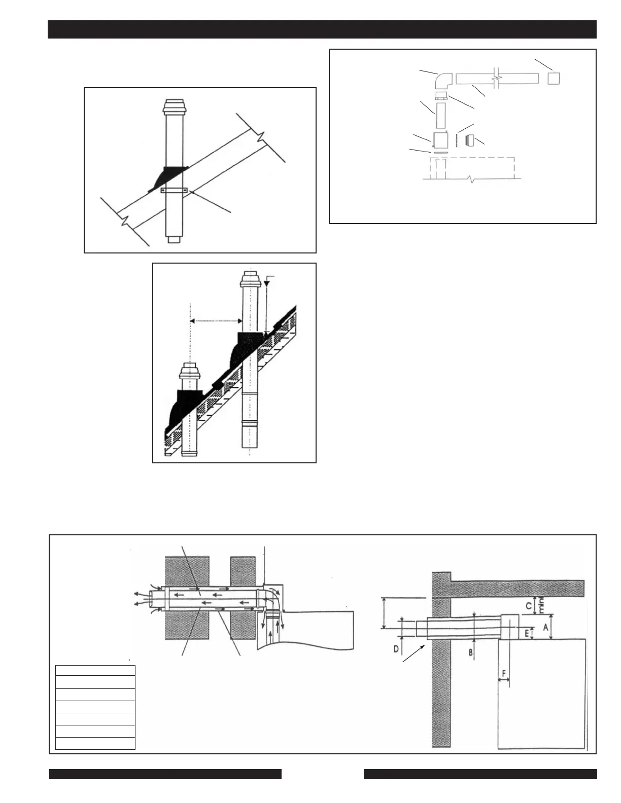
After the area of termination has been selected use part number
#2206 and install vent termination utilizing support bracket
included with kit. (See Fig. 3)
3. Separated Exhaust & Inlet Air in 3" PVC
In a situation where it is desirable to route the venting in a non-
concentric fashion, use part #9530A as seen in Fig. 5. This kit
will allow for the exhaust to be piped independently of the
intake.
The venting then can be continued in 3" PVC for intake air,
and 3" CPVC for exhaust air. Termination then can be piped in
a conventional manner. Inlet and outlet should be in the same
wind plane.
The flue/combustion air system piping should be installed
observing the following criteria:
• For vent lengths in excess of 30 feet, contact MPI
• For each 90º elbow used in the flue system, subtract 3.3
feet from the total allowable length.
• For each 45º elbow used in the flue system, subtract 1.65
feet from the total allowable length.
• Horizontal runs of the flue system must pitch down 5/8"
per foot of length towards the heating system to facilitate
proper flue products condensate drainage.
• Termination of a horizontal flue system shall not be less
than 6 feet above walkway. Take care to minimize the
likelihood of flue/combustion air intake blockage. Vertical
flues must intake and discharge above the snow line.
• Do not place the flue terminal less than 3.3 feet from a
ventilation hole or opening in a building.
• Termination should be at least 2 feet above the snow line.
• All flue-piping components must be assembled to
provide an airtight flue/combustion air system.
INSTALLATION AND TECHNICAL
Termination of a
vertical flue must
provide at least 12
inches (30 cm)
above the roof jack
to the combustion air
intake collar. If there
are two units in the
installation with
vertical flue systems,
the termination of the
systems must be
separated by 16
inches (40 cm). (See
Fig.4)
s mmuusstt
9501 KIT FLUE
• BI-DIRECTIONAL VENT KITS: USE FOR TWO PIPE APPLICATIONS
• ALLOWS FOR 3" PVC VENTING
• THIS ARRANGEMENT CAN BE TERMINATED THROUGH WALL
LEFT, RIGHT, OR REAR
Fig. 5 9530A
3" Elbow, CPVC
Trim so that reducing
bushing fits snug on
top of box.
Bi-Directional box
Gasket
2.5" X 9 Long pipe CPVC
Locking ring
3" Coupling CPVC
4’ of 3" CPVC pipe
3" X 2.5" Reducing bushing
3" Male threaded apapter CPVC
Support bracket
(included with kit)
Fig. 3
Fig. 4
30 cm - 12”
Minimum
40 cm
16”
Minimum
mm
138.0
110.0
152.4
75.0
70.0
67.0
Inches
5.43
4.33
6.00
2.95
2.76
2.64
A
B
C
D
E
F
mini
Dimensions
6%
slope
back to
system.
5/8” per
foot of
run.
Intake pipe 1”
overhang
Air inlet 4.33”
(PVC dia. 110)
Flue gas outlet 2.95”
(PP dia. 75)
Drain slope towards inside 5/8” per foot
Inspection hatch screw