25
www.monitorproducts.com
MONITOR PRODUCTS, INC.
THIS DRAWING IS FOR REFERENCE ONLY. IT
IS NOT INTENDED TO DESCRIBE A COMPLETE
SYSTEM. EACH SYSTEM SHOULD BE DE-
SIGNED BY A PROFESSIONAL.
SIZE FSCM NO. DWG NO. REV
SCALE
SHEET
BALL VALVE
PURGE
/DRAIN
VALVE
Heat Exchanger
for Pool Heat or
Snow Melt
MZ Heating
System
3 Way Valve
Chiller
Heating System
Supply
Zone 2
Radiant Heat or other
Low Temp Heat
Storage Tank
BS Tank
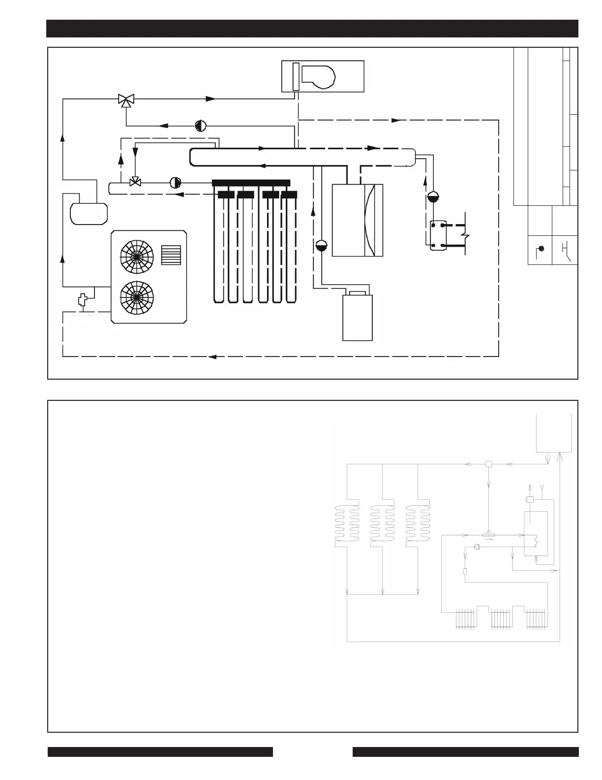
TWO-TEMP SYSTEM WITH SINGLE HIGH-TEMP CALL. FOR USE WHEN TOTAL, DESIGN SPACE-HEAT LOAD IS GREATER THAN 80% OF SYSTEM OUTPUT.
MZ systens used in high-temp, low-temp system with high-temp being “piggybacked” through the priority function of MPI’s DHW kit.
This arrangement uses an indirect DHW tank as a buffer.
A 3-way valve*
B low-temp radiant
C Anti-scald mix valve** on outlet of
DHW tank set at 120 F. max.
D DHW out
E cold potable in
F BS or other indirect tank
G high-temp zone pump
H zone valve for high-temp zone
I monoflow tee ensures flow
cooperation between DHW and high-
temp heat
The high-temp zone’s thermostat is two stage. Stage 1 activates zone valve. The valve’s
end switch brings on the pump, G. The second stage is wired in parallel with the aquastat
in the tank and brings on the MZ’s burner if needed.
Control for the low-temp zones B can be whatever would otherwise be used, including outdoor
reset. Constant circulation recommended.
When there is a high-temp zone call the pump will circulate water from the tank’s heat exchanger
through the zone until the call is satisfied. The tank acts as a buffer. As the tank’s temp falls, the
stat’s second stage brings heating system on.
This arrangement prevents tank overheating at times when no high-temp zone call is
needed. The indirect tank aquastat should be set at whatever temp would be normal for that
family’s use. 110 to 120 F. is normal. The thermostatic mix valve C MUST always be used
to prevent scalding.
There is no conflict between simultaneous DHW and high-temp zone use because high-temp
zone call is above the mix temp of C. Simultaneous use will lengthen the time the MZ will
run to satisfy, but will not interfere with comfort.
If there is a large hot tub or multiple high-flow shower heads, additional DHW storage or more heating system BTUs would be needed in any case. High-temp design must
be at 170 F. or less. If higher temps required, contact MPI. There is no flow conflict between the high-temp zone and the MZ when both priority (DHW / high-temp) circuits
are calling at the same time. The flows are “coupled” only through the indirect tank’s heat exchanger. Flow rates will change depending on whether one or both are calling,
but each circuit will be free to perform its function without interference.
* included in MPI’s DHW kit, part # 9523 ** MPI part # 9075
Note that this is not a design for a specific job. It is a schematic representation of fluid flow patterns suitable for some combined low / high temperature hydronic systems. It shows
one way of solving one of the design challenges normal to combining low and high temperature requirements in hydroninc heating. This drawing is for reference only. It is not
intended to describe a complete system. Each system should be designed by a professional.
A
MZ
D
E
C
H
B
I
F
G
APPENDIX A