9
www.monitorproducts.com
Important note about altitude: Since atmosphere thins
as altitude increases, there is less oxygen available to
support combustion at high altitude. The combustion-air
ALTITUDE ADJUSTMENT
1) Fire heating system. Let run for five minutes. Measure and
set CO at 30 PPM for natural gas (50 PPM for LP gas ).
There is a tapping in the vent elbow inside the MZ’s cabinet
just to the left of the flue-gas exit from the MZ for flue gas
measurement. Note that the cap that covers the gas valve’s
adjustment screw must be in place when CO measurement
is made.
2) Take cover off of air-pressure switch. With heating system
running, jump contacts so that heating system continues
to fire when switch opens.
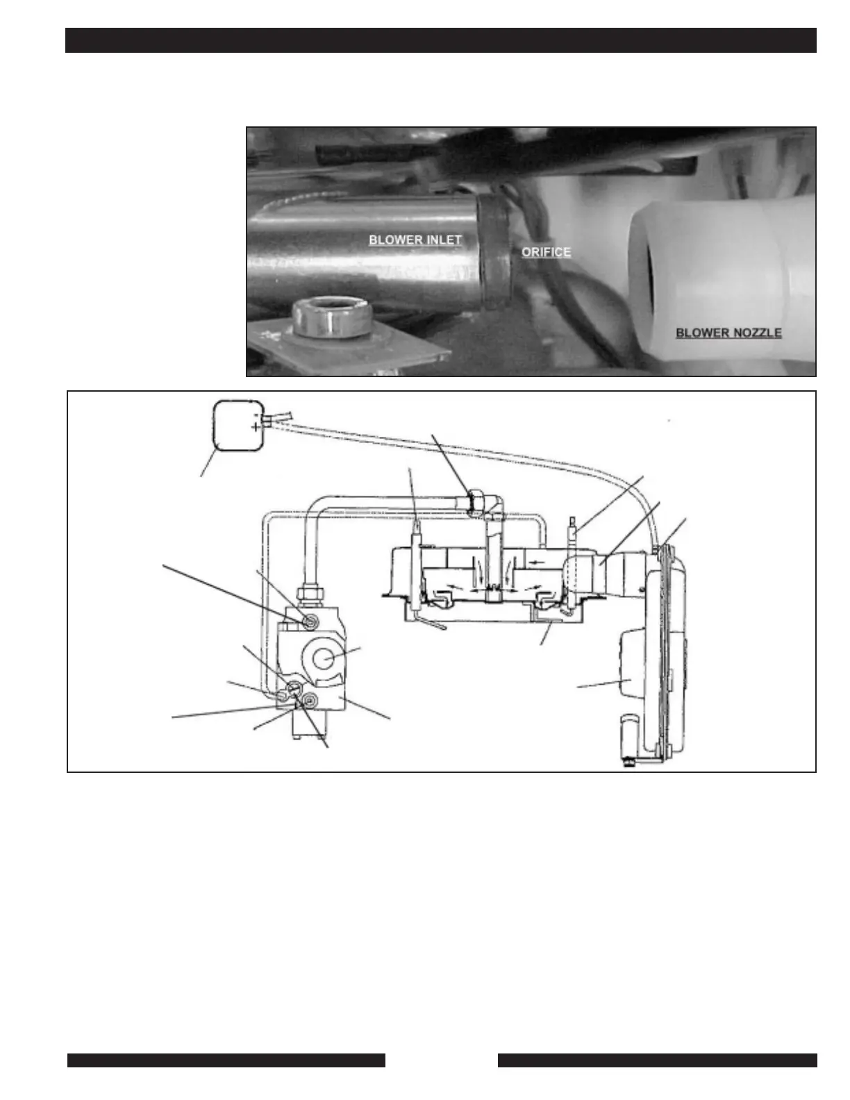
3) Very, gradually block inlet air to blower with something light
and stiff, such as a credit card, until CO reads between
500 and 750 PPM. (NOTE: Blocking half of the blower
inlet may raise CO only slightly. As the critical point of
blockage is reached where CO does begin to ramp up, a
very small increase in blockage makes a very large
increase in CO. It is best to increase blockage VERY
slowly.) Remove jumper wire from switch. Burner will go
out and CO will begin to fall.
4) Adjust air pressure switch VERY, gradually counter
clockwise to the point where the switch closes, which will
then cause the burner to relight.
5) Unblock blower inlet air.
6) CO measurement should then return to 30 PPM for natural
gas ( 50 PPM for LP.) Check to verify that CO is normal.
7) Replace terminal cover on air-pressure switch, replace plug
in vent pipe, replace MZ cover. Cycle unit to verify normal
operation.
INSTALLATION AND TECHNICAL
blower used on the MZ
was designed specifically
for the MZ. Its normal
operating speed is partly
determined by the density
of the air moving through
it. As altitude increases,
the MZ’s blower spins
easier and faster in-
Combustion Chamber
unit pressure
Gas orifice is located in gas-line side of union. Spray union with penetrating
oil and tap wrench to locate nut on union. Gas line may need to be reamed
to accept LP orifice for MZ40.
Air pressure switch
Ionization probe
Outlet pressure
MZ25 Nat. 2.8
MZ25 LP 5.5
MZ 40 Nat or LP 2.8
Pressure
Tap P2
Gas
pressure
regulator
Servo-
system
Pressure
Tap P1
Solenoid
Inlet pressure
must stay within 5”
and 7” WC for
Natural Gas and
11” and 13” WC
for LP gas
Gas valve
To avoid pressure, remove cap, turn adjustment screw
clockwise to increase, counter clockwise to decrease.
Cap must be on to measure.
Ignition accelerator
Air fan
Ignition electrode
Air orifice location
Air pressure switch
test point
creasing the amount of air. The MZ can be used up to 6,000
feet dependinc on vent length of run, aAbove 6,000 feet,
adjustment of the air-pressure switch is necessary.
ALTITUDE
ADJUSTMENT
DIAGRAM