15
www.monitorproducts.com
ELECTRICAL:
• Electrical connections and control strategies, including
the summer / winter switch.
The installation must conform to one or more of the following,
as applicable:
A.) Local codes or, in the absence of local codes, the National
Fuel Gas Code, ANSI Z 223..
B.) Canada-CGA B149 installation code and/or local
installation codes.
C.) The National Electrical Code ANSI/NFPA No. 70.
D.) CSA Standard C22.1 and Canadian Electrical Code PZ.1.
ELECTRICAL CONNECTIONS FROM SITE
The heating system, when installed, must be grounded in
accordance with local codes or, in the absence of local codes,
with the National Electrical Code, ANSI/NFPA 70 and the CSA
Standard Canadian Electrical Code C22.1.
The MZ is designed for 120 volt, 60 cycle, three-wire (load,
neutral, and ground) current and draws about 112 watts in
full operation. The electric supply should be from a dedicated
15 amp circuit.
The MZ is easy to wire. Trim the minimum amount of material
from the pyramid-shaped grommets in the MZ’s cabinet so
as to provide a snug fit for all wiring in and out of the MZ. Run
low and high voltage wires through the strain reliever on the
left side of the control panel, through the chase and into the
control panel. Make sure polarity is correct or the unit will lock
out right after lighting.
There are 2 black jumper wires going into 3 terminals to the
left of the high voltage block. From left to right they are T3,
T2, & T1.
Note: If both jumpers are left in place, the pump will run
continuously and the MZ will maintain the aquastat
setting controlled by the adjustable black knob on the
MZ’s control panel.
Jumper position and the summer/winter switch have no effect
on a priority zone, or a Domestic Hot Water call coming in to
the MZ through the wiring harness that is part of the DHW kit.
If you desire constant circulation in the heating (winter) mode
(water moving through the “B” side of the 3-way valve at all
times if MPI’s DHW Kit is used for prioritizing or if the MZ 25S
is used) and the thermostat or heating system control firing
the burner as needed, then leave the jumper in T1, T2 and the
heating system control in T2, T3. Constant circulation has
multiple benefits. We recommend designing for constant
circulation whenever practical.
T3 T2 T1
N L
120V-60HZ
T3 T2 T1
N L
120V-60HZ
T
INSTALLATION AND TECHNICAL
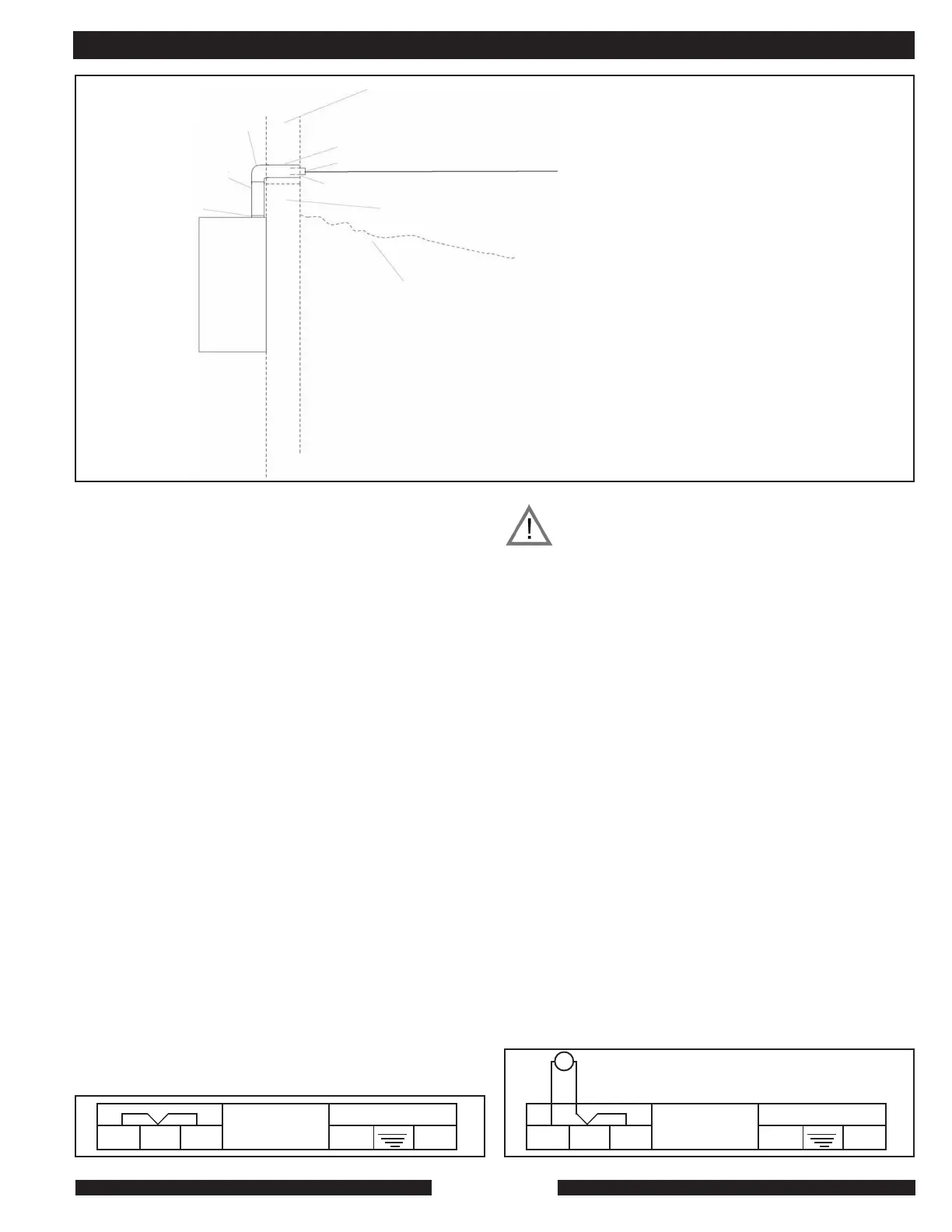
Part 9520,
Flue Adaptor
to Plastic Run
Part 9504, Horizontal
I-meter Stick, Cut to
Length if Necessary
Part 9503,
Horizontal 90
Degree Elbow
MZ
HEATING
SYSTEM
Exterior Wall
Part 9501, Horizontal Flue Termination Kit, Cut to Length
Products of Combustion Out
Terminal Must Exit at the Depth Above snow Line
Mandated by Local Codes of National Fuel Gas Code.
Combination Air In
Foundation Wall Above Grade
Notes: All flue parts are concentric. They exhaust
the products of combustion through a nominal 2.7”
pipe that is enclosed and supported within a nomi-
nal 4” pipe. The 4” conveys combustion air back
to the MZ.
All flue-pipe connection are gasketed slip-fit. It is
Snow Line
recommended that a lubricant such as soapy water be used to facilitate the slip-fit connection.
The male end of each connection should be inserted into the corresponding female end until it
bottoms out.
All flue components should drain back to the MZ.
The MZ an all of its flue parts are zero-clearance to combustibles.
If the terminal point of the MZ as shown in this drawing is below the local snow line, use appropri-
ate numbers of parts 9503 and 9504 to raise the terminal point. Local codes determine flue
distance above snow line. Always terminate with the terminal end of our 9051. Always terminate
in the horizontal plane. The horizontal system will not work in a configuration in which the termi-
nal end of part 9501 is in a vertical position.
Caution: The 24 volt transformer supplied
with the MZ is only intended to operate the
heating system components. If zone
valves are being used an auxiliary
transformer of the proper VA rating must
be installed separately. Please see zone
valve manufacturers data sheets for proper
transformer sizing and wiring
recommendations. Attaching zone valves
to heating system transformer will cause
damage and will void warranty.