27
www.monitorproducts.com
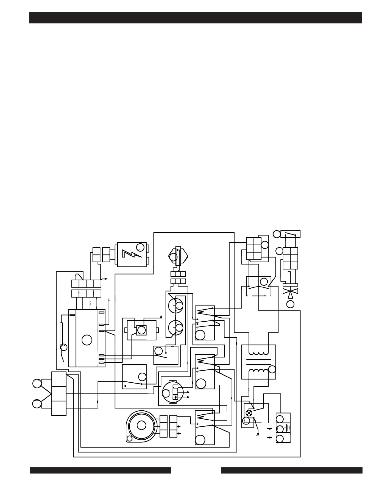
APPENDIX A
Note: In the MZ 25S the wiring harness 27 and the aquastat 6 are installed in
the MZ factory. For an MZ25C using MPI’s DHW kit, part #9523, the additional
aquastat that ships with the wiring harness 27 and 3-way valve 7 must be field
installed inside the MZ and wired in series between 10 and 11.
Component Key [MPI Part Numbers]
1) Line (120 V.)
2) Ground
3) Neutral (common)
4) On-off switch
5) Summer (S) winter (W) switch
6) Field-supplied external close-on-fall switch for DHW or other priority call
7) Three-way value [Part of DHW kit 9523
8) Adjustable aquestat for system-water temperature control
9a) Thermostat location for control of pump and burner simultaneously.
9b) Thermostat location for control of burner. Pump runs continuously
10) Manual-reset flue-gas limit [9051]
11) Manual-reset supply-water limits [9023]
12) Air proving switch [9073]
13) DHW relay [9001]
14) Water pump [9006]
15) Combustion-air fan [9019]
16) Water-flow proving switch [9039]
17) Gas valve [9005]
18) Ignition transformer [9020]
19) Fan relay [9001]
20) Ignition module [9016]
25) Flame-proving rod [9003]
27) Wiring harness for priority control [Part of DHW kit: 9523]
41) Water-pump relay [9001]
42) 120/24 V. Transformer [9043]
Sequence of Operation: Space-Heat Call
On-off switch 4: on. Summer-winter switch 5 (SWS): winter. 24v @ T1 through
SWS. 24v @ T2 brings on pump 14. 24 @ T3 goes through adjustable supply-
water aquastat 8, water limit 11, to flue limit 10 air-proving switch is closed, 24v
closes fan relay 19. At air-proving switch 12 close, 24v at ignition module 20
initiates combustion by powering gas valve 17 while powering spark through
ignition transformer 18. At four-seconds into ignition sequence, flame-proving
is checked through proving rod 25. If flame is proved,
heating system then supplies
heat until call for heat or DHW is satisfied. If leaving-water temperature exceeds
setting on aquastat 8 burner will shut off until supply-water temperature falls
below its setting until the call for heat has been satisfied.
Sequence of Operation: Priority (DHW) Call
On-off switch on. Switch 6 closes on fall, brining 24v to relay 13 which calls for
pump through relay 41 and initiates ignition sequence, bypassing stage one of
aquastat 8. Call for heat is thus available through wiring harness 27 whether of
not unit is in between 10 and 11 to protect manual-reset supply-water limit 11
from nuisance trip.
9B 9A
17
20
8
18
25
15
14
12
19
41
13
10
11
16
4
42
1
32
5
27
7
27
6
T3
T2
T1
4
3
2
1
4
3
2
1
1
1
2
2
1
2
3
2
2
3
3
1
2
3
1
1
3
6
2
5
1
4
3
6
2
5
1
4
MZ 25C - 25S Wiring Diagram
o
o
o
b
bl
b
bl
w
b
r
w
w
g
gray
gray
g
g w
g w
Fan
Fan
Relay
Pump
Relay
DHW
Relay
Pump
br
br
r
b
brr
r
r
r
r
r
gray
gray
br
br
o
o
o
o
o
o
o
o
Air
Proving
Switch
Water Flow
Switch
gray
Lead Gas
Valve
r
Valve
Valve (GND)
24 V.
24 V. Ground
Ground
(Burner)
Senior
o
gray
gray
Transformer
On
Off
Switch
w
w g
r
b
b
b
gray
b
b
br
1
2
0
V
2
4
V
n L
n L
120 V. 60 HZ
br
b
Wire color-code: mote arrows signify return to ground green and neutral (white).
b = black bl = blue br = brown g = green gr = gray
L = line n = nueteral o = orange r = red w = white
Summer
Winter