28
MZ INSTALLATION & MAINTENANCE
9B
9A
17
20
8
18
25
15
14
12
19
41
13
10
11
16
4
42
1
32
5
27
27
b
6
T3
T2
T1
4
3
2
1
4
3
2
1
1
1
2
2
1
2
3
2
2
3
3 1
2
3
1
1
3
6
2
5
1
4
3
6
2
5
1
4
o
o
o
b
bl
b
bl
w
b
r
w
w
g
gray
gray
g
g w
g w
FAN
FAN
RELAY
PUMP
RELAY
DHW
RELAY
PUMP
br
br
r
b
br
r
r
r
r
r
r
gray
gray
br
br
o
o
o
o
gray
o
o
o
AIR
PROVING
SWITCH
WATER FLOW
SWITCH
gray
LEAD GAS
VALVE
r
VALVE
VALVE (GND)
24 V.
24 V. G
ROUND
GROUND
(BURNER)
S
ENIOR
o
gray
gray
TRANSFORMER
ON
OFF
SWITCH
w
w g
r
b
b
b
gray
b
br
br
1
2
0
V
2
4
V
n L
n L
120 V. 60 HZ
br
b
Wire color-code: mote arrows signify return to ground green and neutral (white).
b = black bl = blue br = brown g = green gr = gray
L = line n = nueteral o = orange r = red w = white
Summer
Winter
b
b
br
44
LAG
VALVE
RELAY
br
b
w
LAG GAS
VALVE
30
o
b
br
1 2
br
RELAY
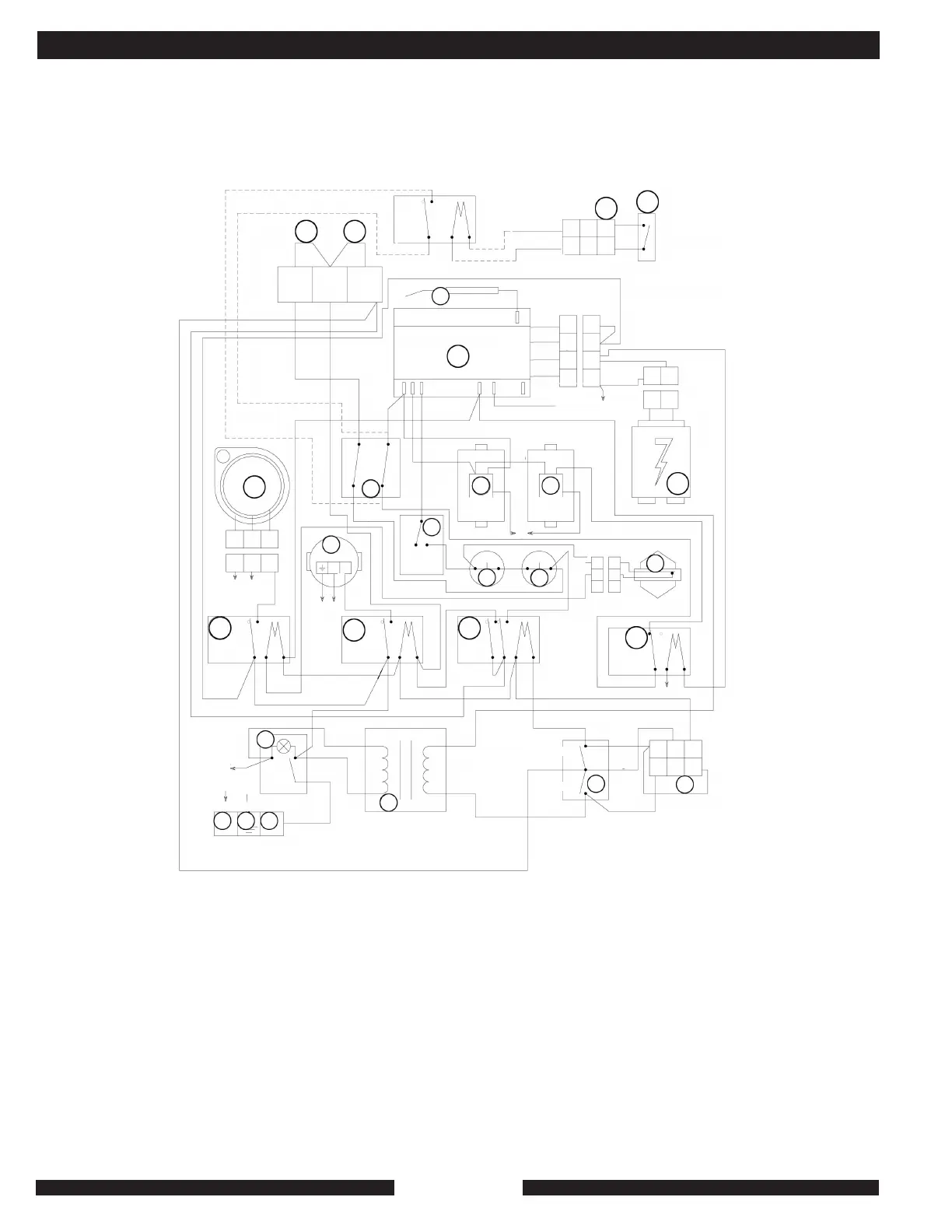
Note that the additional relay to bring full output to a priority call is field installed. Note that the grey and black wires used to
power the additional relay are also used to power the 3-way valve when MPI’s 3-way valve kit, part # 9523, is used for
prioritizing. If prioritizing is done through a pump-control switching box, use MPI part # 9518, wiring harness, item #27 in this
drawing, to connect the MZ to the additional relay and priority-controller end switch.
Note that the relay shown is available from MPI as our part # 9001. The use of the transformer in the MZ to power other
relays or other controls is not recommended.
WIRING DIAGRAM FOR FULL OUTPUT CONTROL OF MZ2040C FOR PRIORITY CALL WHEN ADJUSTABLE-LIMIT
SWITCH IS AT LOW-TEMP SETTING.
APPENDIX A