16
MZ INSTALLATION & MAINTENANCE
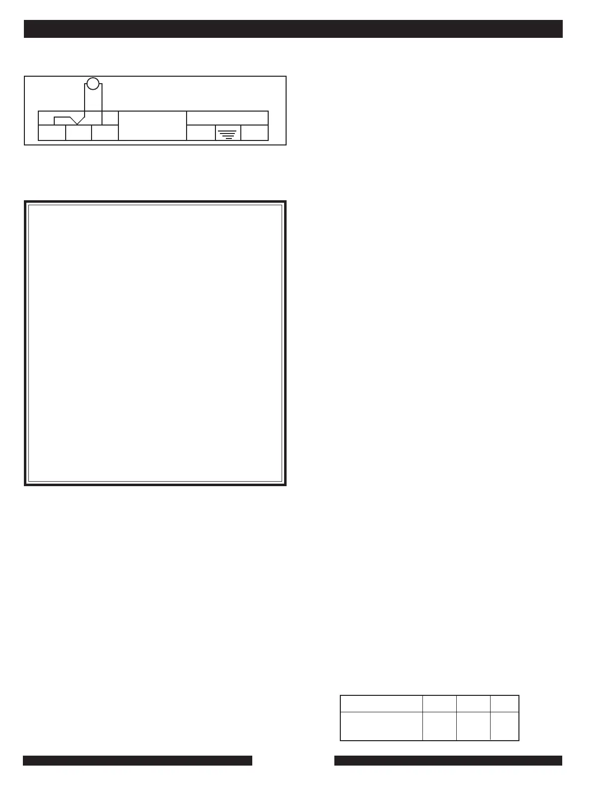
T3 T2 T1
N L
120V-60HZ
T
To call for burner and pump at the same time, leave the jumper
in T2, T3 and the heating system control in T1, T2.
With the heating system’s summer/winter switch in the
summer (sunshine symbol) position, the heating system will
not respond to a call for heat from a space heat thermostat or
other space-heat control.
! AT T E N T I O N !
No attempt should be made to connect electrical
wires to any other location except
1. The indirect hot water storage tank wiring kit,
which plugs into the terminal socket on the right
side of the control panel cluster; and which also
includes strap-on aquastat to be installed inside
the MZ and wired in series with the MZ’s built-
in high limit flue and leaving water safety limits.
(See page 18).
2. Two-stage external control of MZ 20-40C.
NOTE: Two-stage operation of the Model MZ40C
is automatic: On a call for heat, both burners fire.
When return water temperature gets to between
9º F to 14º F of the setting on the adjustable
aquastat on the face of the
heating system, the 2nd
stage shuts off and the 1st stage runs until the
heat call is satisfied. If return-water temp falls, the
second stage comes back on.
PREPARATION FOR USE/INITIAL START-UP:
Should overheating occur or the gas supply fail to shut off,
turn off the manual gas control.
Do not use this unit if any part has been under water.
Immediately call a qualified service technician to inspect the
unit and to replace any part of the control system or any gas
control, which has been under water.
Before initial start up of the unit, the installer should:
• Check that the gas circuit is leak free.
• Carefully flush out the gas pipes. Where the installation is
new, the purge serves to evacuate the air that is contained
in the pipes so that the unit has sufficient fuel. The presence
of air in the gas prevents the burner from lighting and results
in the flame control unit safety device cutting in. This applies
to a new installation running on either natural gas or LP.
For the latter, the storage tank must also be properly
flushed before initial start up.
ATTENTION! All necessary safety precautions should be
taken when venting the gas.
Flushing the gas will also have the effect of removing any oxide
particles from the pipes produced during brazing.
• Check that the flue outlet and air intake is leak free and
unobstructed.
• Check for the appearance of the flame through the round
observation window inside the hinged door just above the
controls.
• Check that the installation is filled with water. The water
pressure should equal 12 PSI.
The MZ heating system has two air purge valves, one on the
heating outlet, the other on the domestic hot water heater (25
S model dual-functioning unit).
• Check that the electricity supply is connected correctly:
120 V-60 Hz, with correct polarity.
• Check that the siphon trap is filled with water. Check that
the condensate outlet is connected.
• Make sure the circulator is running. If not, remove cap
covering shaft and manually start. The adjustable domestic
hot water thermostat is factory set on the MZ 25S. If it
becomes necessary to adjust this position it’s
recommended that for energy efficiency the setting be kept
at the minimum water temperature consistent with the
consumer’s needs. The maximum DHW temp is 145°. Keep
in mind there is a hot water scald potential if the thermostat
is set too high.
COMMISSIONING:
When operating the unit for the first time, the installer must
verify:
• That the gas valve works properly;
• That the flame control works properly;
• The burner setting: CO, CO2, and gas valve settings
are correct.
1. Open the manual valve on the gas inlet.
2. Switch on the main heating switch, or circuit breaker.
3. Set the lighted on/off switch on the control unit to the “on”
position.
4. Put the circulating pump switch to the “winter” position
(snowflake). In the “summer” position (sun), the circulating
pump only works when the domestic hot water tank
requires heating (MZ 25S or C models with indirect hot
water storage tank).
FLOW VERIFICATION:
In order for the MZ to function properly a minimum amount of
water must flow through the MZ’s heat exchanger to remove the
heat being produced. There is a flow switch inside the MZ that
will not allow the MZ to fire unless there is minimum flow.
Approximate external feet of head available from the Grundfos
UPS1542 in the MZ25 series heating system at flow rates shown.
GPM 3.5 4 6
Speed 3: FT of 12 10 5
Head Available
INSTALLATION AND TECHNICAL