8
MZ INSTALLATION & MAINTENANCE
eliminated. Oxygen and minerals in the water coming in to
replace the water leaking out will damage the MZ.
CORROSION:
The MZ should be filled with clean, clear, neutral ph water
suitable for drinking. A cleaning solution such as a mixture of
water and trisodium phosphate should be used in any systems
with oily residues. Many chemicals have been used over the
years in existing heating systems that could cause
premature failure of MZ units. It is important that no additives
be used in the system water for the MZ other than BIONIBAL,
which is supplied with each unit.
IMPORTANT: The use of a 2% by volume solution of
BIONIBAL in a radiant-heating system using non-oxygen-
barrier tubing will protect the MZ and the system to which it is
connected, from oxygen corrosion. In a system using tubing
with an effective, intact, oxygen barrier or in a hard-piped
system, a 1% solution of BIONIBAL is sufficient. BIONIBAL
doesn’t deteriorate or weaken over time, but should be
renewed if system is drained.
Under no circumstances should standard commercial anti-
freeze solutions be used in the MZ. Most of them contain
corrosion inhibitors that are not approved for use in the MZ.
They will cause heat exchanger failures that are not covered
by warranty. No other additives for lubrication, leak stoppage
or any other purpose can be used in the MZ. To do so will
void all warranty.
FREEZE PROTECTION:
In situations where freeze protection is a necessity. MPI ships
5 gallon quantities of BIONIBAGEL anti-freeze which is
formulated with Bionibal at a concentration that will bring a
50/50 mix of BIONIBAL and water to a 1% concentration of
BIONIBAGEL. If the application does not require a 50/50 mix,
the addition of sufficient BIONIBAL to bring the resulting
solution to a 1% concentration is important, otherwise bacterial
growth and corrosion may take place. In non-barrier systems,
which we discourage, a 2% concentration of BIONIBAL must
be assured. One quart (part # 9526) and 2.6 gallon (part
#9519) quantities of BIONIBAL are available from MPI.
Note that the addition of glycols to the water passing through
the MZ changes the rate at which the mix absorbs and
releases heat, decreasing its effectiveness as a heat transfer
fluid. Glycols also increase the viscosity of the water, making
it more difficult to pump. These factors can significantly
influence the overall performance of the heating system and
should be taken into account in the system’s design.
in an easily accessible place. The pipe supplying gas to the
heating system must not cause a pressure loss great enough
to decrease inlet gas pressure below the specified minimum
gas pressure values. (5" of water column for natural gas, 11"
for LP.) After initial start up, check that the pressure tapping
points are properly closed and check the general leak
tightness of the gas circuit. Always purge through the gas
pipe work before initial firing of the unit (in order to get rid of
any particles produced by welding or threaded joints).
The unit and its individual shut-off valve must be disconnected
from the gas supply piping system during any pressure testing
of that system.
NOTE: Many commonly used,
unapproved corrosion inhi-
bitors CAN DAMAGE THE MZ
AND VOID THE WARRANTY.
GAS PIPING:
The supply line is 3/4" NPT, and
enters at the lower left side of the
unit as shown.
The gas supply pipe must be fitted
with a 1/ 4 turn stop valve located
EXAMPLE PIPE SIZING TABLE
For gas flow through various pipe lengths and diameters.
(FOR REFERENCE ONLY)
Note: Table above is for natural gas with specific gravity 0.60
with a pressure drop through the gas piping of 0.30" w.c. Refer
to ANSI Z223.1 for additional pipe sizing.
Pipe length
(feet)
10
20
30
40
50
75
100
150
1/2"
132
92
73
63
56
45
38
31
3/4"
278
190
152
130
115
93
79
64
1"
520
350
285
245
215
175
150
120
1 1/4"
1050
730
590
500
440
360
305
250
Capacity of pipe for pipe size (ft3/hr)
NATURAL GAS TO LP GAS CONVERSION AND
HIGH ALTITUDE ADJUSTMENT:
Each MZ is supplied with a LP conversion kit. Follow steps
for conversion from Natural gas to LP:
1. Loosen the nut from the gas line/burner junction as shown on
next page (there are 2 on the MZ40C). Insert orifice into gas
line. Note that since there is no natural gas orifice in the MZ40C,
the tightening of the union between the gas line and the elbow
sometimes narrows the opening in the gas line for the orifice.
If that occurs, ream the opening. For MZ40C LP heating
systems, insert orifices before mounting heating system.
2. Reconnect nut and tighten.
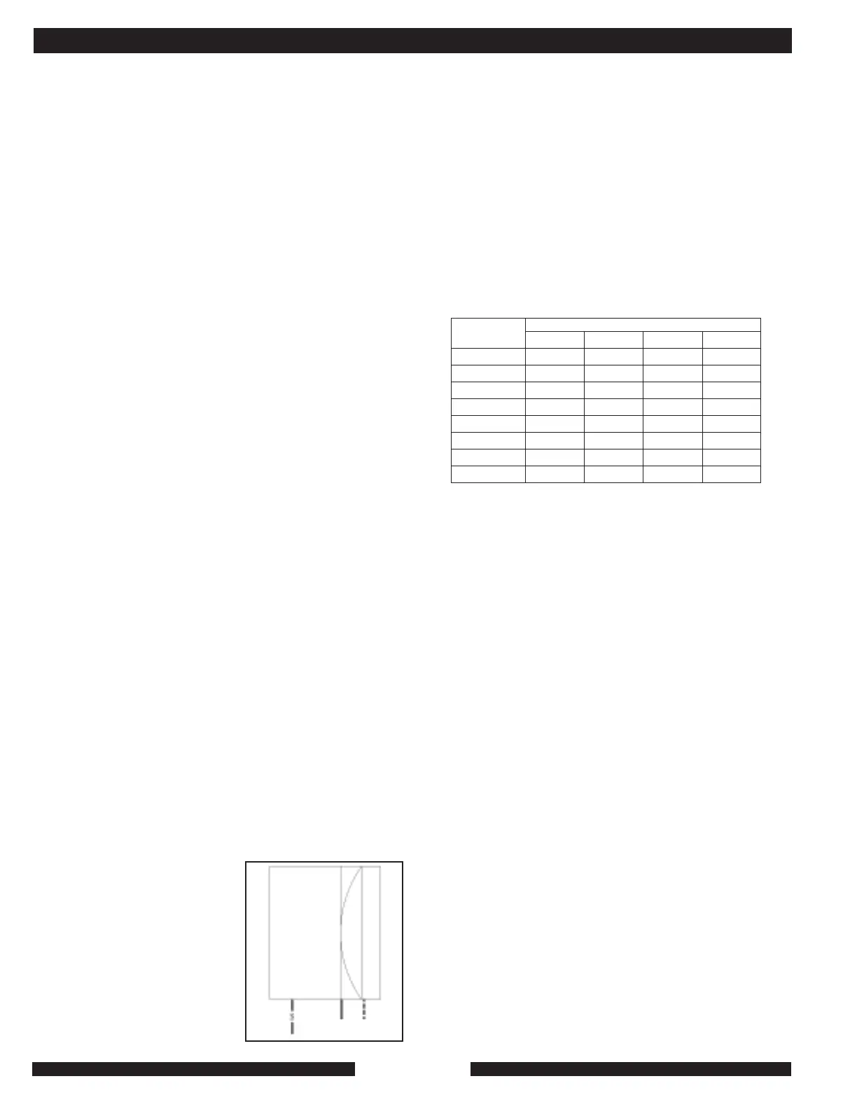
3. For MZ25C/S models only: Remove the combustion air
fan by pulling it to the right. Disconnect the rubber air hose
and the wiring. Set the fan aside. Note: The split-ring LP
orifice slips into the burner, as shown below. If it fits loosely,
use the appropriate tool to open the split-ring LP orifice so
that it holds in place.
4. Inlet gas pressure for LP gas must be between 11" and 13"
water column with the heating system running. The MZ40C
requires no gas valve change. The MZ25C/S requires a gas
pressure adjustment from the factory 2.8" water column
setting to 5.5". The adjuster is under the slotted cap on the
gas valve. Turn the adjustment screw underneath the cap
full clockwise and then back off one turn counter-clockwise.
Replace cap. The heating system should then fire, permitting
outlet pressure measurement. Repeat adjustments until the
correct outlet pressure of 5.5" is reached. The final pressure
reading at tap P2 must be taken with the unit running and
the cap reinstalled on the gas valve.
INSTALLATION AND TECHNICAL
MZ
Heating
System
ÍGas Inlet