7
www.monitorproducts.com
For steady water temperatures, the DHW water flow rate
through the MZ25S must be high enough to keep the MZ’s
burner on. If the user complains of DHW temperature swings,
especially in the shower, install a thermostatic mixing valve
between the hot and cold legs of the system. Make sure it is
a thermostatic, not a tempering valve. Also make sure that
the temperature setting of the MZ25S is at least 15° above
the desired mix temperature of the thermostatic valve (even
if it means a higher than needed gpm valve is used), or there
may be temperature fluctuations.
NOTE: The DHW performance of the MZ25S is not exactly
like that of a regular hot water heater, so make sure that you
or your customer understand its limitations. Filling a bathtub
will take longer, since most wide open spigots will not yield
hot enough water for a comfortable bath. The filling process
will have to be slowed in order to keep the temperature up.
Make sure your customer knows this! If space is not critical,
it is almost always better to use an MZ 25C and one of our
BS tanks. The cost of the tank and valves are little more than
the difference between the 25S and 25C. It has been our
experience that those people who choose the MZ25S do so
for the exceptionally high efficiency for overall DHW as
compared to conventional standing-pilot, gravity-vented gas
water heaters, and easily adjust to the subtle differences.
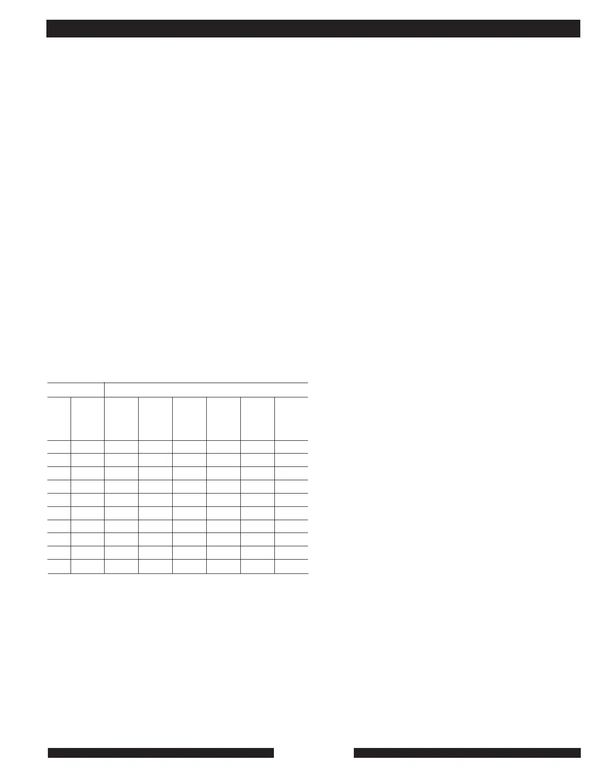
Table 1 may be helpful in balancing MZ25S DHW systems.
APPROXIMATE DHW PERFORMANCE OF MZ25S AT
VARYING FLOW RATES AND INLET WATER
TEMPERATURES. ALL TEMPERATURES ARE IN
FAHRENHEIT.
First column gives flow in gallon per minutes.
At any steady gallons per minute (GPM) flow rate, the MZ
will raise the temperature of the inlet water by a specific
amount. That temperature rise is shown in the second column.
Third, and subsequent columns, gives inlet water temperature
rising 5º F increments (top row) and the leaving domestic hot
water (DHW) temperature (remaining rows.)
GPM
1.5
1.75
2.0
2.25
2.5
2.75
3.0
3.25
3.5
3.75
Temp
Rise
105
90
79
70
63
57
52
48
45
42
35 F.
Inlet
Water
Temp
140
125
114
105
98
92
87
83
80
77
40 F.
Inlet
Water
Temp
145
130
119
110
103
97
92
88
85
82
45 F.
Inlet
Water
Temp
-
135
124
115
108
102
97
93
90
87
50 F.
Inlet
Water
Temp
-
140
129
120
113
107
102
98
95
92
55 F.
Inlet
Water
Temp
-
145
134
125
123
112
107
103
100
97
60 F.
Inlet
Water
Temp
-
-
139
130
128
117
112
108
105
102
Table 1
MZ25S Leaving water Temperatures, Degree F.
CONDENSATE:
Condensate removal can be accomplished by letting it drain
into the building’s normal drain or septic system. The MZ’s
condensate output depends on the return water temperature
of the heating system. Colder return water means higher
efficiency and more condensate. Over time condensate will
eat concrete, iron and copper drains. Most drain water is
alkaline which will neutralize condensate. Percolating
condensate through crushed limestone will neutralize it. If no
gravity drain available, an acid-proof condensate pump will
do the job.
CHARGING & LEAK TESTING:
It is assumed that the system into which the MZ is being
installed is a leak-free system. Leaks in the system will
damage the heating system and void the warranty. If there are
leaks in the system, fresh water will have to be added to the
system to replace the lost water. The addition of fresh water,
over time, will always bring air and dissolved minerals into the
heating system and will dilute the corrosion inhibitor. All of
which will cause a failure.
The proper concentration of BIONIBAL corrosion inhibitor (1%
by volume for all metal pipe systems and systems with oxygen
barrier tubing, 2% by volume for non-barrier systems) that is
shipped with the MZ will completely protect the MZ and the
system it is connected to from corrosion if kept at the right
strength. BIONIBAL does not deteriorate over time or get used
up over time. Additional Bionibal is available form MPI.
Once the system is properly charged with:
• Water
• BIONIBAL, or
• Water, glycol BIONIBAL mixture, it should remain stable
indefinitely.
Before the MZ is connected, the piping system should be
filled with clean, neutral P-h water to a pressure of 100 PSI. If
there is no change in pressure after 24 hours, the system
can be assumed to be leak-tight. The system should also be
visually inspected as thoroughly as possible. If any leaks are
found, they must be repaired.
The MZ has a brass, male-hose-thread, fill-and drain valve
operated by a stainless-steel ball valve. We recommend that
the MZ not be permanently piped to the structure’s potable
water system, unless local code requires auto fill. If auto-fill
is installed to the system, our recommendation is that it be
turned off. The flow switch in the MZ prevents low-water firing.
It is normal for heating systems to lose a very small amount
of water over time through valve stems or similar fittings. This
trivial amount of water can easily be replenished during normal
maintenance. There is a clear plastic tube in the MZ that fits
over the nozzle on the air vent and prevents the water that typically
spits out of the nozzle from staining the inside of the MZ.
On start up, the MZ should be run in the heating mode until
the entire system is brought up to operating temperatures.
Do not leave city water pressure on the auto-fill during normal
heating system operation since any system leaks will cause
the Bionibal corrosion inhibitor to be diluted and eventually
INSTALLATION AND TECHNICAL