26
MZ INSTALLATION & MAINTENANCE
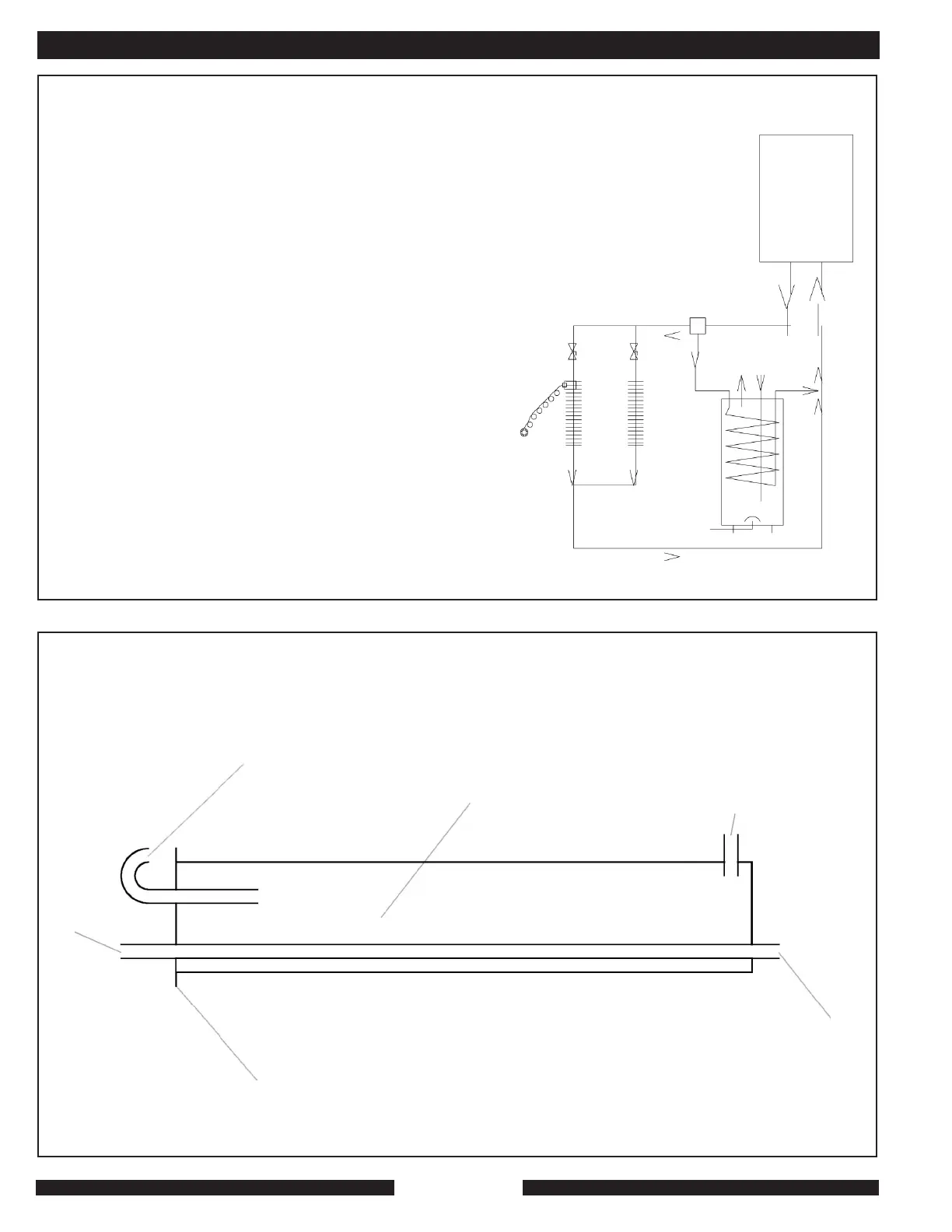
A 3-way valve, part of MPI’s DHW kit, part# 9523. When the aquastat in the DHW storage tank (B) calls for heat, the 3-way valve in the MZ will switch to the DHW position
and the MZ will fire and run until the aquastat is satisfied. When the DHW call is finished the 3-way valve moves to the space-heat position.
B DHW storage tank. (MPI BS tank. 25, 40, 50 or 80 gal.)
C Balancing valve.
D Thermostatic modulating zone valve.
E Master zone containing thermostat.
F Street or well water in.
G Potable DHW out.
H DHW re-circ pipe in BS tank for optional re-circ loop.
Note that there should be a properly-anticipated standard thermostat in zone M. (Call this the “master”
or “reference” zone. It controls supply-water temperature automatically.) When the summer-winter
switch on the MZ’s control panel is in the winter mode, the 85-watt pump in the MZ will circulate
constantly, feeding either the space-heat zones or the DHW call. When the switch is in the summer
mode, the MZ will only respond to a DHW call.
The thermostat automatically modulates the supply water temperature in the winter mode. The
slave zone will always see system-water flow at the temperature determined by the stat in the
master zone. The slave zone, controlled by D, can be set back cooler than the master zone. To
increase temperature in the slave zone, use a balancing valve to reduce flow to the master zone
gradually.
For maximum efficiency, reduce flow through the MZ as much as possible to the point where the
flow switch in the MZ is no longer satisfied or where comfort in very cold weather is compromised
because the MZ is trying to make heat, but is cycling on its adjustable high-limit control.
Note that reducing flow through the MZ means that the last foot of baseboard in a long run can be
much cooler than the first foot when the burner is on for a long time. If baseboard runs through
several rooms in secession, the baseboard should be sized carefully. The MZ can operate at a 50
deg. F. delta T. between return and supply. That’s great for efficiency, but does mean that baseboard
sizing has to be done right.
Contact MPI for more information. There are many ways of getting great efficiency and comfort.
NOTE: This schematic is a generic example of a concept, not a system design. The person using
this concept in any design must take full responsibility for the function of the system. Each system
will be different. This drawing does not show numerous details required for good practice and local
code compliance. Please contact MPI for more information if necessary.
MZ
25C
C
C
D
G
E
H
A
B
F
APPENDIX A
Existing chase (for instance,
chimney, after cleaning)used for
flue and intake-air runs.
Continuous 3" PVC run for
intake-air is preferred,
especially if very clean chase
cannot be assured. DO NOT
USE CHLORINATED
CLEANERS FOR CHASE
CLEANING!!!
All pipe 3" PVC. Connect to
MPI’s accessory #9530 A,
separated vent kit.
Combustion-air to MZ
Flue gas from MZ
Cap.
MZ VENTING USING
CHASE FOR INLET AIR.
Fresh air intake
Flue gas out.