Design Guide
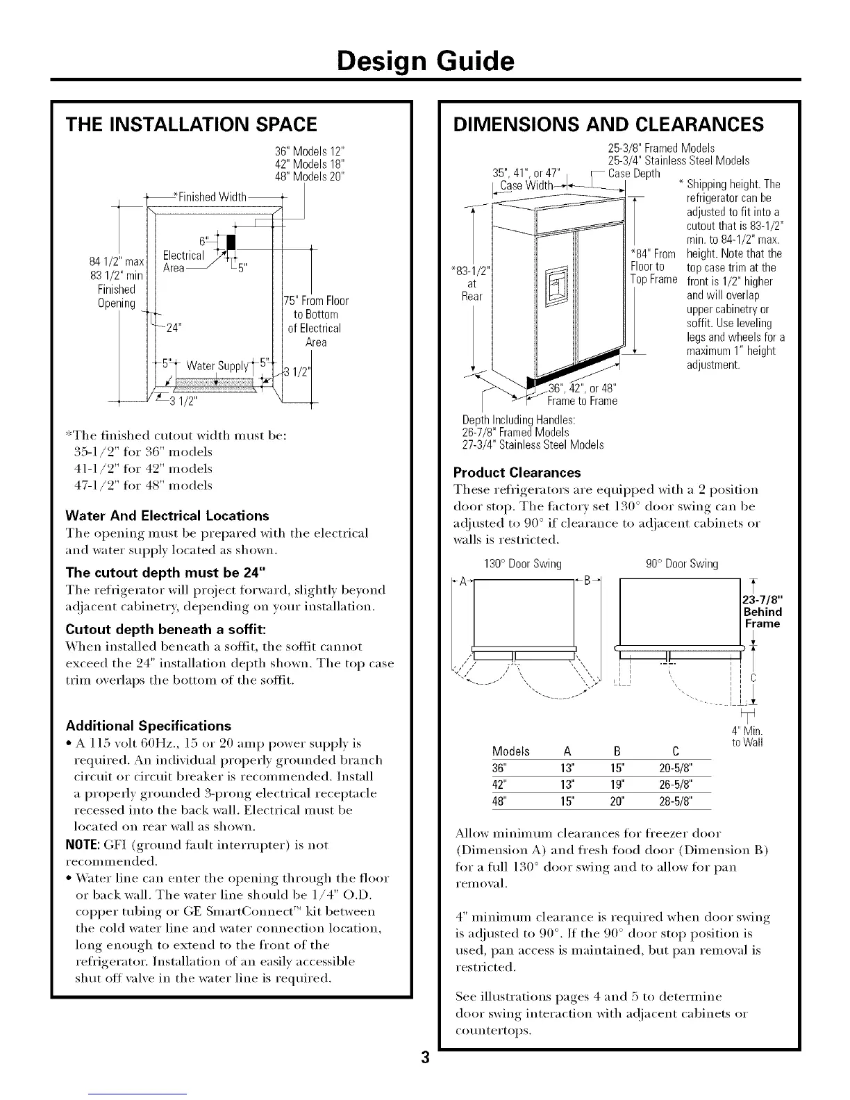
THE INSTALLATION SPACE
36"Models12"
42" Models18"
48" Models20"
_ _Finished Width_ J
AreaElectdc X15 l
841/2" max, , ^ J L'"
831/2,,minII
Finished ][
Opening ] [ 75"FromFloor
[_5 to Bottom
24" ff Electrical
Area
WaterSupply_ 5%
/ I)
3i/2"
*The finished cutout width must be:
35-1/2" fin" 36" models
41-1/2" for 42" models
47-1/2" fin" 48" models
Water And Electrical Locations
The opening must be prepared with the electrical
and water supply located as shown.
The cutout depth must be 24"
The refrigerator will project fin'ward, slightly beyond
ac!jacent cabinetry; depending on wmr installation.
Cutout depth beneath a soffit:
When installed beneath a soffit, the soffit cannot
exceed the 24" installation depth shown. The top case
trim overlaps the bottom of the soffit.
Additional Specifications
• A 115 volt 60Hz., 15 or 20 amp power suI}ply is
required. An individual properly grounded bran(h
circuit or circuit breaker is recommended. Install
a propedy grom_ded 3-prong electrical receptacle
recessed into the back wall. Electrical must be
located on rear wall as shown.
NOTE: OF] (grotmd fault interrupter) is not
recoi/lillended.
• _&_ter line can enter the opening through the floor
or back wall. The water line should be 1/4" O.D.
copper tubing or GE SmartConnect'" kit between
the cold water line and water connection location,
long enough to extend to the front of the
refrigerator. Installation of an easily accessible
shut off wflve in the water line is required.
DIMENSIONS AND CLEARANCES
_83-1/
at
Real
25-3/8" FramedModels
25-3/4" StainlessSteelModels
_84"From
Floorto
TopFrame
Shippingheight.The
refrigeratorcanbe
adjustedto fit intoa
cutoutthat is 83-1/2"
min.to 84-1/2"max.
height.Notethat the
top casetrim at the
front is 1/2"higher
andwill overlap
uppercabinetryor
soffit. Useleveling
legsandwheelsfor a
maximum1" height
adjustment.
.36", 42",or48"
Frameto Frame
DepthIncludingHandles:
26-7/8" FramedModels
27-3/4" StainlessSteelModels
Product Clearances
These refi'igerators are equipi)ed with a 2 position
door stop. The thctorv set 130 ° door swing can be
ac!justed to 90 ° if clearance to ac!jacent cabinets or
walls is restricted.
130° DoorSwing
_'-4...... / ,... .)_
90° DoorSwing
i
T
23-7/8"
Behind
Frame
Models A B C
36" 13" 15" 20-5/8"
42" 13" 19" 26-5/8"
48" 15" 20" 28-5/8"
4" Min.
to Wall
Allow minimmn clearances fin" fl'eezer door
(Dimension A) and fl'esh fi_od door (Dimension B)
fl)r a flfll 130 ° door swing and to allow fl_r pan
YeIlloval.
4" minimmn clearance is required when door swing
is ac!justed to 90 °. If the 90 ° door stop position is
used, pan access is maintained, but pan remowfl is
restricted.
See illustrations pages 4 and 5 to determine
door swing interaction with ac!jacent cabinets or
COtlntertol) s.