Do you have a question about the Monogram ZIS42 and is the answer not in the manual?
Disconnect power before servicing and handle electrical checks with care.
Do not interfere with or bypass any engineered features, parts, or devices.
Use specified GE Appliances parts or equivalent for replacements to ensure performance.
Verify all connections, wire dressing, spacing, grounds, water, and panel reassembly before power.
Consult the GE Appliance Service Handbook for additional safe servicing practices.
Do not attempt repairs if unsure about safe and satisfactory completion.
Explains risks like shock, burns, fire, flood from improper servicing.
Use this manual with the product's Mini-Manual for comprehensive model information.
Electrical data, schematics, and wiring diagrams are in the Mini-Manual.
Details on providing a 115 volt electrical receptacle and precautions when disconnecting the power cord.
Requirements for connecting copper tubing to the water valve and water supply line pressure.
Ensuring the refrigerator is level (zero tilt) front-to-back and side-to-side using rollers and adjustment bolts.
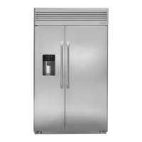
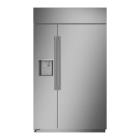
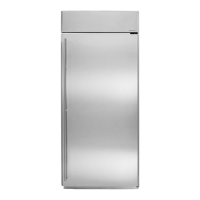
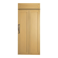
Information on custom-made decorative panels for doors, top, and sides, and caution regarding servicing them.
How the top panel is mounted using a trim frame, locator pins, and slotted brackets for adjustment.
Procedure for removing custom door panels by accessing screws after removing handles and trim.
Description of the plastic base panel attached to the cabinet with screws for access.
Location and function of freezer and fresh food temperature controls, recommended settings, and stabilization time.
An electrical temperature control sensing air supply to regulate compressor run time.
An automatic air damper control sensing air temperature to regulate cold air supply.
Location and function of the energy saving switch to eliminate moisture on the case flange.
Automatic icemaker cycles can be stopped by raising the feeler arm; ice production rate.
Recommendation to remove the top panel and clean the condenser when servicing.
Detailed explanation of the refrigerant path from compressor through condenser, dryer, loop, evaporator, and back to compressor.
Instructions for pulling the chassis forward and cautions about kinking refrigeration tubing.
Optional removal of the hood for additional access to the refrigeration system during installation.
Location, mounting, and terminal configuration of the compressor in the unit compartment.
Location of the overload protector mounted directly on the compressor common terminal.
Location of the solid state (PTC) relay mounted on compressor start and run terminals.
Location and specifications (MF) of the run capacitor for 36/42 and 48" models.
Description of the condenser construction (5/16-inch copper tubing) and mounting location.
Description of the condenser loop construction (1/4-inch copper tubing) and its non-replaceable nature.
Purpose and connection of case flange/mullion and auxiliary heaters for preventing dew point issues.
Location of the dryer in the unit compartment, connected between condenser and condenser loop, and to the capillary.
Description of the heat exchanger (capillary and suction tube) and its insulation for protection.
How the condenser fan circulates air through the unit compartment for cooling the condenser and compressor.
Mounting, access, and removal procedure for the condenser fan motor and blade.
How the evaporator fan circulates cold air within the freezer compartment.
Distribution of cold air to the fresh food compartment via a duct and air damper control.
Mounting location of the evaporator fan assembly and procedure for accessing/replacing the motor and blade.
Explanation of the evaporator fan delay operation and the role of the fan delay thermostat.
Location and removal procedure for the evaporator fan delay thermostat.
Location, mounting, and access for the freezer compartment temperature control and its capillary.
Procedure to test the fresh food damper control by using an ice cube to check its response.
Location, mounting, and removal procedure for the defrost control in the unit compartment.
Securing and access procedure for the defrost heater attached to the evaporator with brackets.
Function and routing of the drain tube from the drain trough to the defrost water pan, and its securing clips.
Location of the defrost water pan at the front of the slide-out chassis, forming a base for the compressor.
Access procedure for fresh food lights by removing the light shield cover.
Location and access for illumination lights in the fresh food compartment's storage bins.
Location and access procedure for the freezer light on non-dispenser and dispenser models.
Location and removal procedure for rocker type light switches in the upper trim above the doors.
Control of the case flange/mullion heater via the energy saver switch; auxiliary heater for failure.
Description of the standard crescent cube icemaker, its mounting, and removal procedure.
Procedure for initiating a test cycle and adjusting the water fill quantity for the icemaker.
Location of the ice storage bin in the freezer compartment on non-dispenser models.
Procedure for completely removing the dispenser recess by removing door end caps and handle trim.
Description of the outer door construction: pre-painted galvanized steel, folded, and toggle-locked.
Description of the inner door construction (ABS) and how door modules are positioned on ribs.
Components of the door assembly (outer, inner door, gasket retainers) are foamed-in-place and not separately replaceable.
Specific steps for freezer door removal on dispenser models, including water tubing and wiring disconnection.
Breaker strips are foamed in place and not replaceable.
Description of the four tempered glass shelves in the fresh food compartment and their positioning.
Number of cantilever wire shelves in the freezer compartment for non-dispenser and dispenser models.
Description of fresh food storage bins made of Lexan, their track and roller system, and two wire storage baskets.
Testing electrical components using wiring harness connectors, an ohmmeter, and a direct start test for the compressor.
Accessing the refrigeration system via service valves for diagnosis using compressor capacity or leak-restriction tests.
| Brand | Monogram |
|---|---|
| Model | ZIS42 |
| Category | Refrigerator |
| Language | English |