One-Net/DASDEC User Manual 2-1v3.0 | r0616
Hardware Connecons
INSTALLATION
The One-Net and DASDEC frames mount in an EIA-compliant equipment rack by means
of four rack screws fastened through the front mounng ears.
For safe, long-term reliability:
• Ensure the ambient air temperature surrounding the EAS device is within the
product’s specied operang temperature range.
• Maintain adequate venlaon within the rack.
• Ensure that adequate space exists on all sides of the frame for sucient airow.
It is recommended a 1RU space be maintained between equipment, to avoid the
transfer of heat between devices.
• Ensure the locaon of the EAS device is accessible, dry, and free of dust.
Rack Units Height Depth Width Weight
2RU 3.50”
(8.89 cm)
12.0”
(30.48 cm)
19.0”
(48.26 cm)
15 lbs
(6.8 kg)
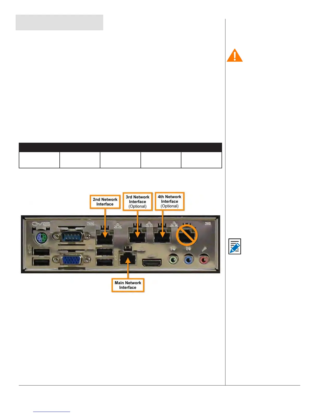
NETWORK CONNECTIONS
Network Connecons
The EAS device comes with two network interface ports (Main and 2nd Network
Interfaces). These are industry standard RJ45 ports, and support standard networking
protocols. The Main Network Interface port is where your inial network connecon
should be established. By default, this is the only acve network interface. The
addional network interfaces must be acvated via the web interface.
More detailed informaon about networking can be found in Chapter 5 - Network
Setup in this manual.
Note
In facilies that require
supplementary network
connecvity, addional
networking hardware
may be installed. This
oponal network
expansion will enable
the 3rd & 4th Network
Interface ports. The
5th network port is
non-funconal, and
is not supported by
this device. Navigate
to Setup > Network
> Conguraon to
congure the network
ports via the web
interface.
Cauon
The rack and screws
should be sucient
to carry the load of
the unit, including the
weight of accompanying
cables. However, it
is recommended a
horizontal lacer bar be
installed behind the
back panel to alleviate
cable stress, ensure
cables stay connected,
and provide eecve
cable management.