42
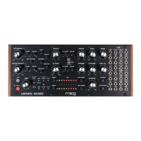
VCF IN
Audio input to the VCF section
AUDIO INPUT: –5V to +5V
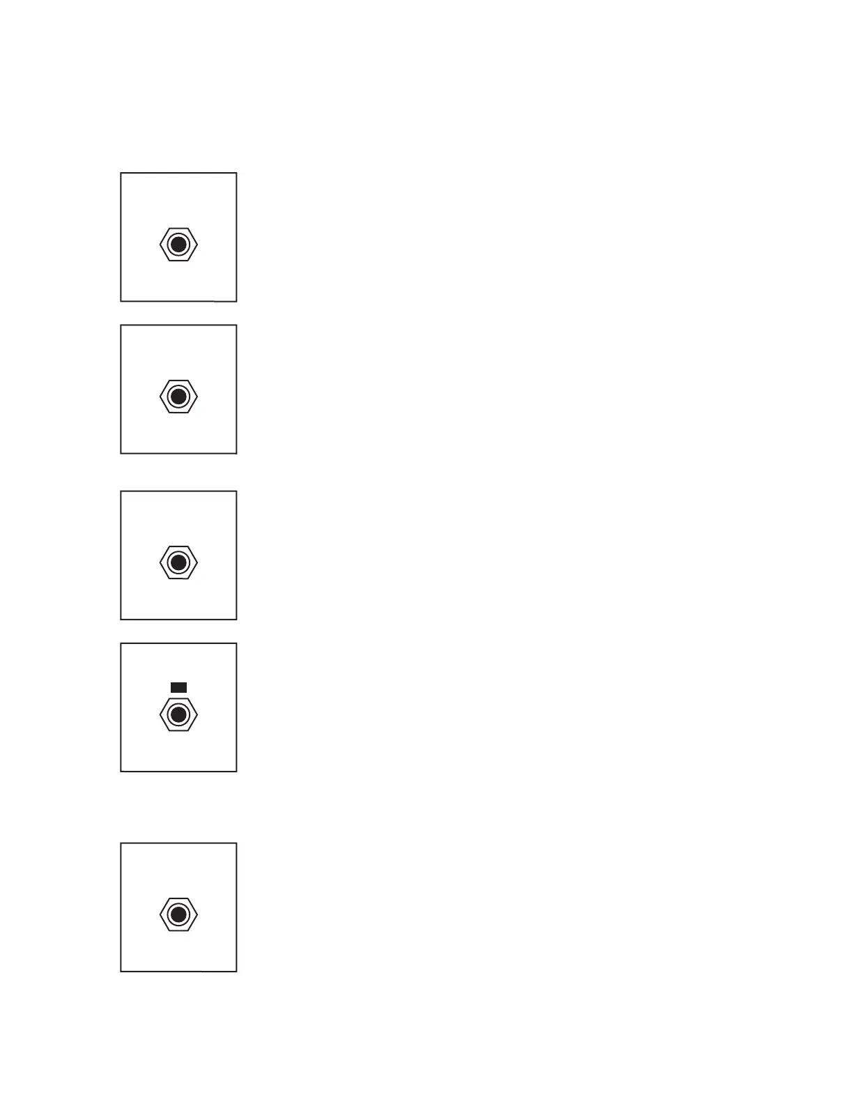
CUTOFF
This is the CV input for the filter CUTOFF. A positive CV input increases the
cuto frequency of the VCF. It is summed with VCF CUTOFF panel control. EG1
is normalled to the input of this jack; patching an external CV will break that
normalled connection. The EG1/CV AMT knob attenuates incoming CV.
CV INPUT: –5V to +5V
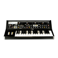
VCF VCA CV
This is the CV input that controls the level of the Voltage-Controlled Amplifier
(VCA) for the VCF section. EG2 is normalled to the input of this jack; patching a
signal to VCF VCA CV will break that normalled connection.
CV INPUT: 0V to +8V
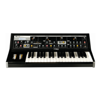
EG2
CV output for EG2
CV OUTPUT: 0V to +8V
VCF VCA CV
EG2
U MIX 1 (RING)
PATCH BAY (Continued)
U MIX 1 (RING)
This is the input for channel 1 of the U MIX mixer. It is DC coupled so that it can
accept either audio or control signals. Its level is controlled by the U MIX 1 LVL
panel control. The RING MOD between the VCO and MOD VCO is normalled
to the input of this jack; patching a signal to U MIX 1 (RING) will break that
normalled connection.
AUDIO INPUT: –5V to +5V
CUTOFF
VCF IN
ROW FOUR
ROW FIVE