MOONEY SECTION VII
MODEL M28J AIRPMNE
AND
SYSTEMS DESCRIPTION
INSTRUMENT PANEL
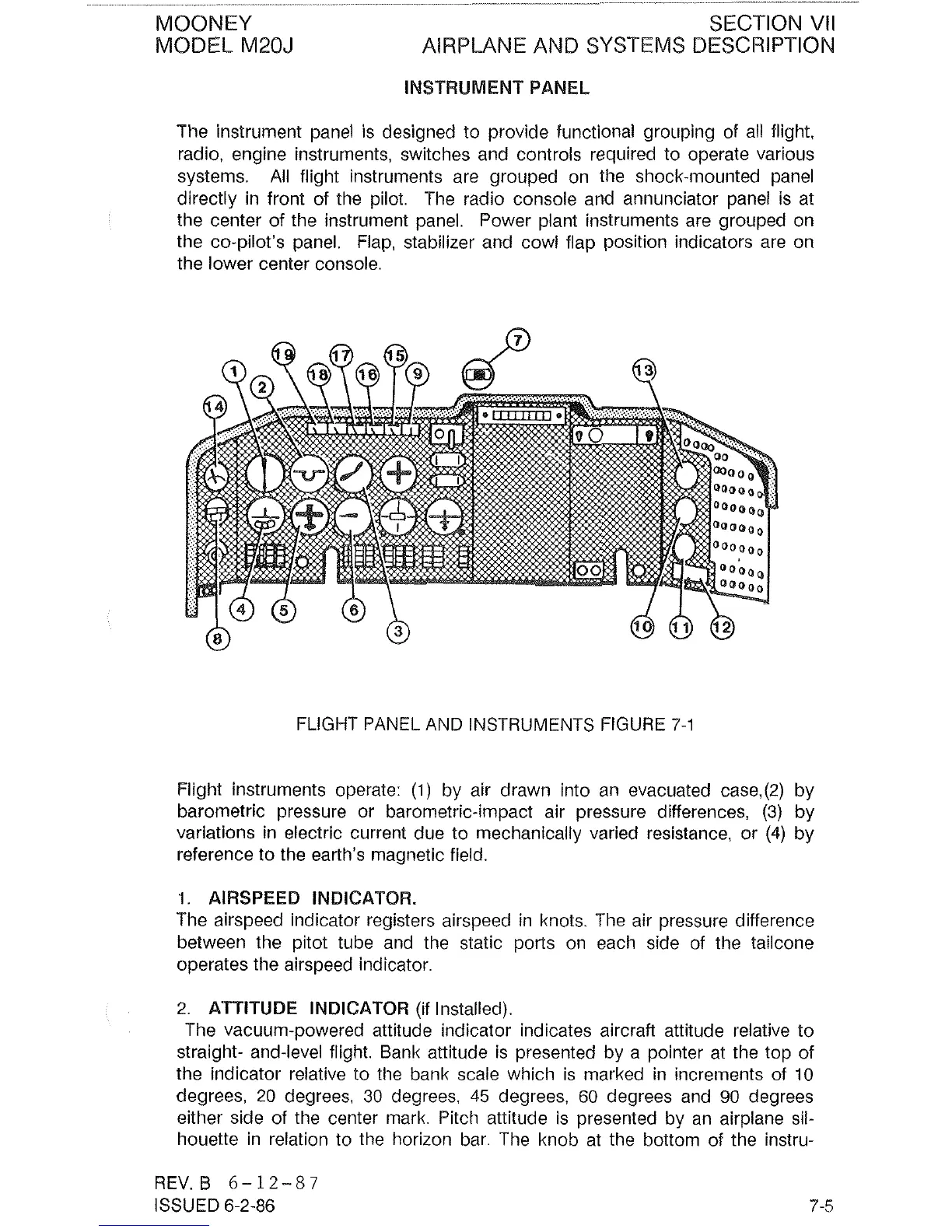
The instrument panel is designed to provide functional grouping of all flight,
radio, engine instruments, switches and controls required to operate various
systems. All flight instruments are grouped on the shock-mounted panel
directly in front of the pilot. The radio console and annunciator panel is at
the center of the instrument panel. Power plant instruments are grouped on
the co-pilot's panel. Flap, stabilizer and cowl flap position indicators are on
the lower center console.
FLIGHT PANEL AND INSTRUMENTS FIGURE
7-1
Flight instruments operate:
(1)
by air drawn into an evacuated case,(2) by
barometric pressure or barometric-impact air pressure differences,
(3)
by
variations in electric current due to mechanically varied resistance, or
(4)
by
reference to the earth's magnetic field.
1. AIRSPEED INDICATOR.
The airspeed indicator registers airspeed in knots. The air pressure difference
between the
pitot tube and the static ports on each side of the tailcone
operates the airspeed indicator.
2.
ATTITUDE INDICATOR (if Installed).
The vacuum-powered attitude indicator indicates aircraft attitude relative to
straight- and-level flight. Bank attitude is presented by a pointer at the top of
the indicator relative to the bank scale which is marked in increments of 10
degrees,
20
degrees, 30 degrees,
45
degrees, 60 degrees and
90
degrees
either side of the center mark. Pitch attitude is presented by an airplane sil-
houette in relation to the horizon bar. The knob at the bottom of the
instru-
REV.B
6-12-87
ISSUED 6-2-86
 Loading...


