535 User’s Manual Chapter 1 3
Introduction
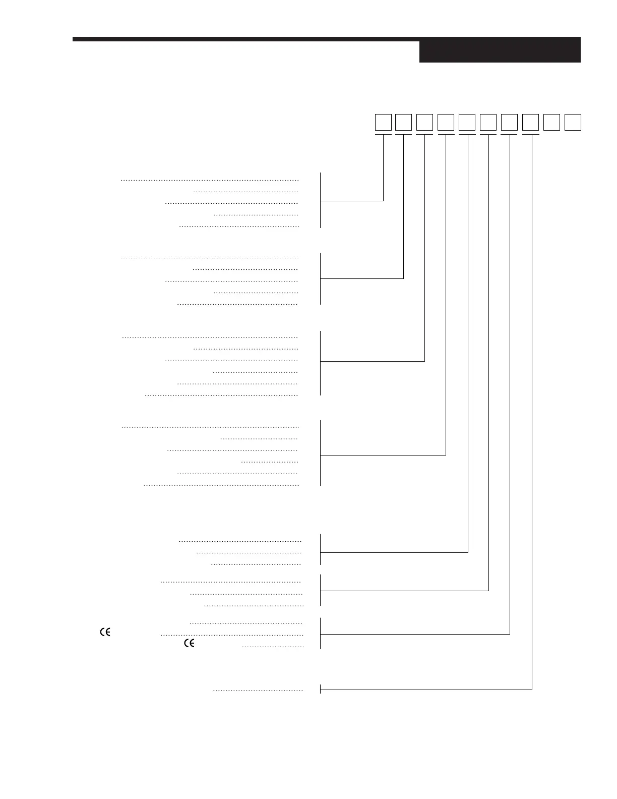
Note 1: Capability for position proportioning output is specifed by ordering 535-11xxAxxx00, 535-33xxAxxx00, or 535-44xxAxxx00. Note 2: Capability for
velocity proportioning output is specifed by ordering 535-11xxxxxx00, 535-33xxxxxx00, or 535-44xxxxxx00.
Note 3: Up to two outputs may be used for
alarms.
Note 4: All outputs are interchangeable modules. Note 5: The mechanical relay and solid state relay modules are derated to 0.5 amp at 24 Vac
when used as the fourth output.
Order
Output 1: Control Code
None 0
Mechanical Relay (5 amp) 1
Analog (milliamp) 2
Solid State Relay (triac) (1 amp) 3
DC Logic (SSR drive) 4
Output 2: Control, Alarm, or Retransmission
None 0
Mechanical Relay (5 amp) 1
Analog (milliamp) 2
Solid State Relay (triac) (1 amp) 3
DC Logic (SSR drive) 4
Output 3: Control, Alarm, Retransmission, or Loop Power
None 0
Mechanical Relay (5 amp) 1
Analog (milliamp) 2
Solid State Relay (triac) (1 amp) 3
DC Logic (SSR drive) 4
Loop Power 5
Output 4: Alarm, Retransmission, or Loop Power
None 0
Mechanical Relay (0.5 amp, 24 V) 1
Analog (milliamp) 2
Solid State Relay (triac) (0.5 amp, 24 V) 3
DC Logic (SSR drive) 4
Loop Power 5
Options
Enter “0” if not desired
Slidewire Feedback for Position
Proportioning Output A
24 VAC/24 VDC Operation F
Slidewire and 24 VAC/24 VDC G
Remote Setpoint B
Profile Controller Option C
Remote Setpoint and Profile E
Set of Five Digital Inputs D
Certification H
Five Digital Inputs and Certification J
Serial Communications
Enter “0” if not desired
RS-485 Serial Communications S
535 – 00
 Loading...