535 User's Manual Chapter 5 41
Controller Set Up
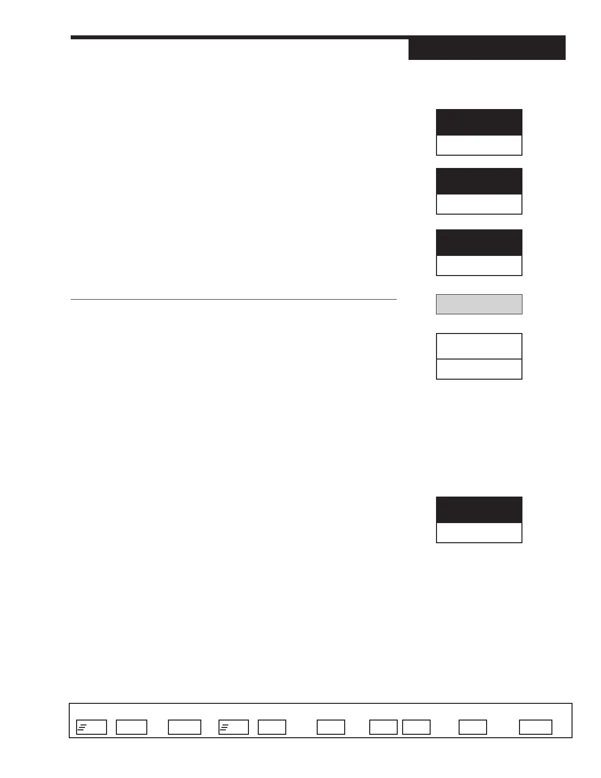
Access Set Up Return to Operation Next menu Next parameter Next value Access Tuning Return to Operation
+
FAST MENU
DISPLAY
+
MENU MENU
▲ ▼
MENU DISPLAYFAST
14. CLOSE F/B
Defines the feedback ohm value corresponding to full close (0% output).
R 0 to S/W RANGE
D 100 Ohms
15. OUT1 STOP
This defines the stopping point for control output 1 when staging outputs.
R 1 to 100%
D 50%
16. OUT2 STRT.
Defines the starting point for control output 2 when staging outputs.
R 0 to 99%
D 50%
ALARMS
1. ALM. TYPE:1
Defines the type of alarm for alarm 1.
• HIGH ALRM.
• LOW ALARM
• HIGH/LOW Separate High & Low alarm setpoints in one
alarm
• BAND
• DEVIATION
• MANUAL Causes an alarm when in manual control
• REMOTE SP Causes an alarm when in Remote Setpoint
• RATE Selects a rate-of-change alarm
D OFF Deactivates the first alarm
2. ALM. SRC:1
Selects the source of the value being monitored by HIGH, LOW or HIGH/LOW
alarm 1.
D PV
•SP
• RAMP SP
• DEVIATION
• OUTPUT
• PV2
ALARMS
ALM. TYPE:1
OFF
CLOSE F/B
100
OUT1 STOP
50
OUT2 STRT.
50
ALM. SRC:1
PV