535 User's Manual Appendix 7 A-23
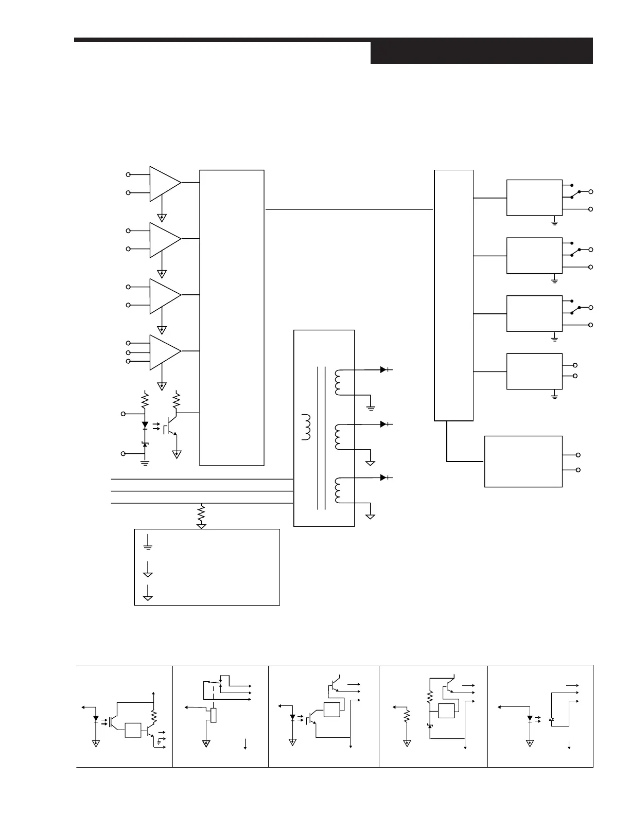
Isolation Block Diagram
APPENDIX 7
ISOLATION BLOCK DIAGRAM
Power
Supply
Line
L
N
G
E
E
Isolated output ground
Earth referenced ground
Internal ground
E
+V
+Vd
+Ve
Digital
Inputs 1-5
Slidewire
Input
RSP
Input
PV2
Input
PV1
Input
Multiplexer
ISO
CPU
Output 1
ISO Ground
Referenced
Output 2
ISO Ground
Referenced
Output 3
ISO Ground
Referenced
Output 4
ISO Ground
Referenced
RS485 Serial
Communications
Interface
1. Each of the three ground circuits are isolated from each other to
withstand a potential of 500 volts for 1 minute, or 600 volts for 1
second.
2. RSP, Slidewire and the PV inputs are isolated to withstand 50
volts peak between each other for 1 minute.
3. Milliamp, Loop Power and SSR Drive modules in output
positions 1, 2, and 4 are not isolated from each other.
Milliamp Module Mechanical Relay
+V
SSR Driver
+V
Loop Power SSR Output


 To Next Page