535 User's Manual Chapter 5 35
Controller Set Up
Access Set Up Return to Operation Next menu Next parameter Next value Access Tuning Return to Operation
+
FAST MENU
DISPLAY
+
MENU MENU
▲ ▼
MENU DISPLAYFAST
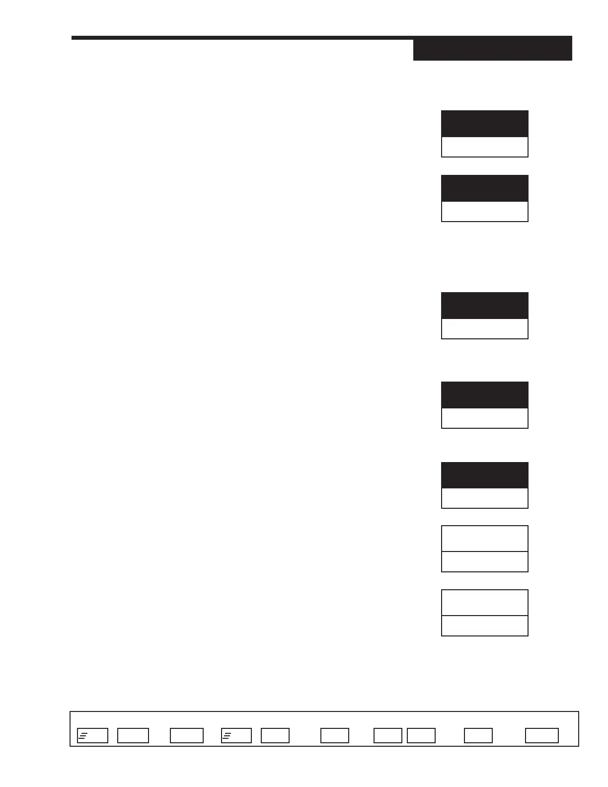
2. DEG. F/C/K
Selects the PV1 temperature units if using a thermocouple or RTD.
D FAHR.
• CELSIUS
• KELVIN
3. DECIMAL
Specifies the PV1 decimal point position.
D XXXXX
• XXXX.X
• XXX.XX
• XX.XXX
• X.XXXX
4. LINEARIZE
Specifies if the PV1 input is to be linearized. NOTE: T/C’s and RTD’s are auto-
matically linearized.
D NONE
• SQR. ROOT Square root linearization is activated.
• CUSTOM 15-point custom linearization curve is
activated.
5. LOW RANGE
Specifies the engineering unit value corresponding to the lowest PV1 input
value, e.g. 4 mA.
R –9999 to 99999 Max. is HI RANGE
D Dependent on the input selection
6. HI RANGE
Specifies the engineering unit value corresponding to the highest PV1 input
value, e.g., 20mA.
R -9999 to 99999 Min. is LOW RANGE
D Dependent on the input selection
7. SP LO LIM.
Defines the lowest setpoint value that can be entered from the front panel only.
R –9999 to 99999 Max. is SP HI LIM. Min. is LOW RANGE
D Dependent on the LOW RANGE value.
8. SP HI LIM.
Defines the highest setpoint value that can be entered from the front panel only.
R –9999 to 99999 Min. is SP LO. LIM. Maximum is HI RANGE
D Dependent on HI RANGE
SP LO LIM.
(D)
SP HI LIM.
(D)
HI RANGE
(D)
DEG. F/C/K
FAHR
DECIMAL
XXXXX
LINEARIZE
NONE
LOW RANGE
(D)