535 User's Manual Chapter 5 37
Controller Set Up
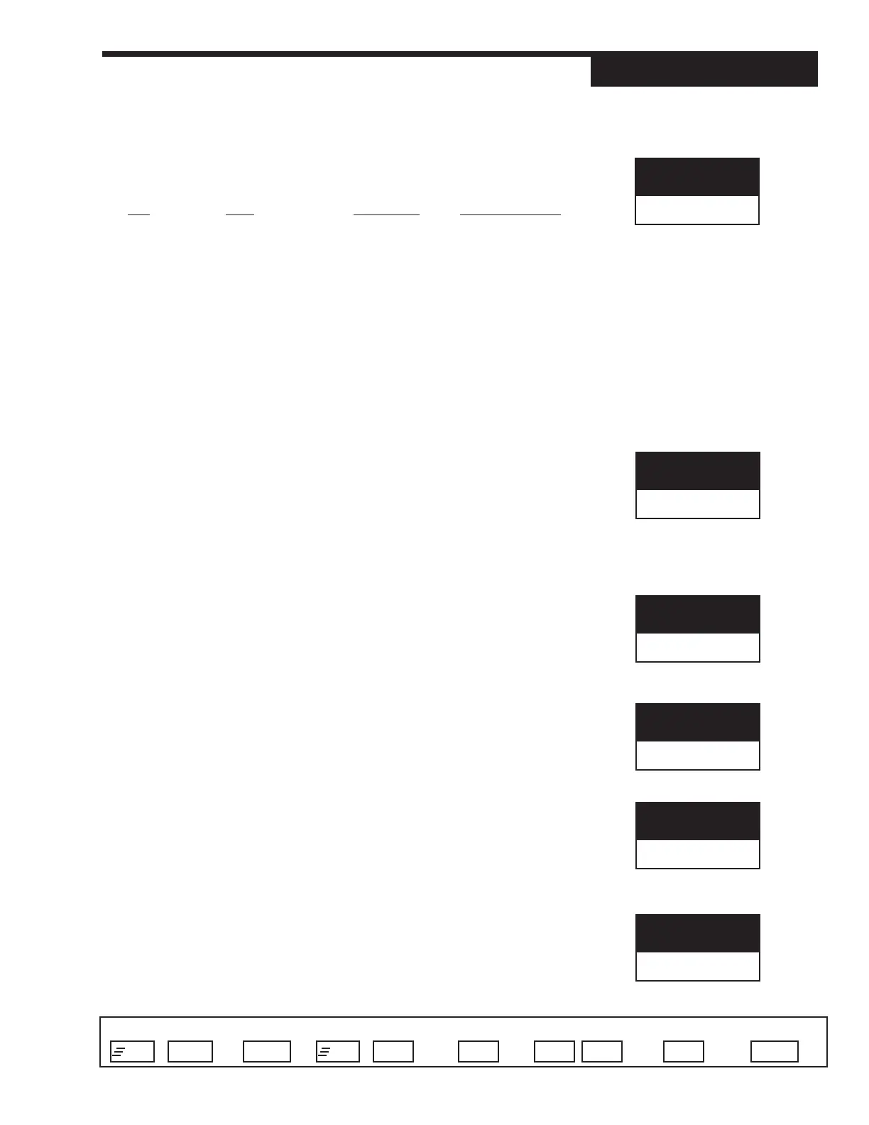
Access Set Up Return to Operation Next menu Next parameter Next value Access Tuning Return to Operation
+
FAST MENU
DISPLAY
+
MENU MENU
▲ ▼
MENU DISPLAYFAST
2. PV2 TYPE
Selects the particular sensor or input range for PV2
T/C RTD VOLTAGE CURRENT (mA)
D J T/C D DIN RTD D 1-5 V D 4-20mA
• E T/C • JIS RTD • 0-5 V • 0-20mA
• K T/C • SAMA RTD • 0-10 mV
• B T/C • 0-30 mV
• N T/C • 0-60 mV
• R T/C • 0-100 mV
• S T/C • +/– 25 mV
• T T/C
•W T/C
• W5 T/C
• PLAT.II T/C
3. DECIMAL
Specifies the PV2 decimal point position.
D XXXXX
• XXXX.X
• XXX.XX
• XX.XXX
• X.XXXX
4. LINEARIZE
Specifies if the PV2 input is to be linearized. Thermocouples and RTD’s are
automatically linearized.
D NONE
• SQR. ROOT Square root linearization is activated.
5. LOW RANGE
Specifies the engineering unit value corresponding to the lowest PV2 input
value, e.g. 4 mA.
R –9999 to 99999 Max. is HI RANGE
D Dependent on the input selection
6. HI RANGE
Specifies the engineering unit value corresponding to the highest PV2 input
value, e.g. 20 mA.
R -9999 to 99999 Min. is LOW RANGE
D Dependent on the input selection
7. FILTER
Setting for the low pass PV2 input filter.
R 0 to 120 seconds
D 0 seconds
PV2 TYPE
J/TC
DECIMAL
XXXXX
FILTER
0
LOW RANGE
(D)
HI RANGE
(D)
LINEARIZE
NONE