www.miinet.com Moore Industries-International, Inc.
- 94 -
User’s Manual
238-741-00K
May 2019
Programmable Smart HART Temperature Transmitter
THZ
3
/ TDZ
3
SECTION 5
Sensor 1 and 2 Two Wire Offset (0.0-250.0) : This setting is to offset the wire resistance of the
2-Wire sensor cable, and will help the accuracy of the measurement.
1. Enter the Offset value you desire.
Sensor 1 and 2 Serial Number:
1. Enter the Serial Number for the device here.
Filter: This setting is used to configure the input filter. The filter is designed to reduce the effects
of mains induced noise. The input filter frequency value should be set to the frequency of the
local AC supply–either 50Hz or 60Hz.
1. Choose either 50Hz or 60Hz filter for your the devices here.
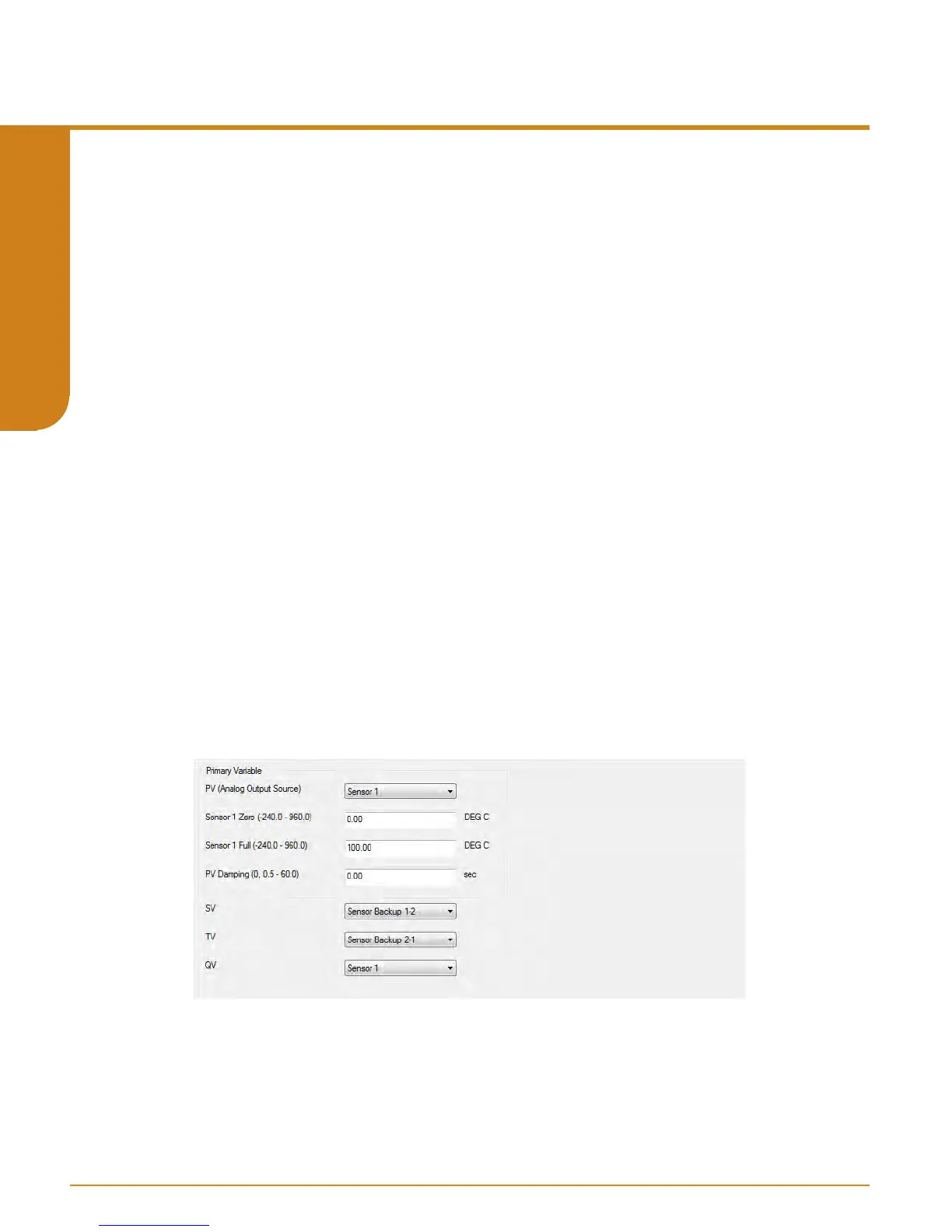
Ranging and Mapping
The Ranging and Mapping menu will allow you to view current Device Variable assignment/
mapping to PV, SV, TV, and QV. It will also allow you to designate or change each one as
needed. To do so enter the Change Variable Mapping menu option. In this menu you will
select from RJC Temperature, Sensor 1, Sensor 2, Backup 1-2, Backup 2-1, Average,
Dierential 1-2, Dierential 2-1, Absolute Dierential, Low Select, or High Select to
each variable (PV, SV, TV, & QV).
Refer to Figure 5.27.
In addition to mapping the Dynamic Variables, you can also set the PV lower range and upper
range values to AO 0-100% and PV Damping. PV Damping allows you to introduce a delay into
the response of your unit in order to stop short-lived spikes from initiating faults and generating
fault messages. The damping time setting is the time PV takes to make a 63% change in
response to a step change.
Figure 5.27. THZ
3
/ TDZ
3
Parameters Input Ranging and Mapping
 Loading...