Performance Adjustment Pages
Operator’s Manual, Morbark Integrated Control System—Model 20 Chipper
26
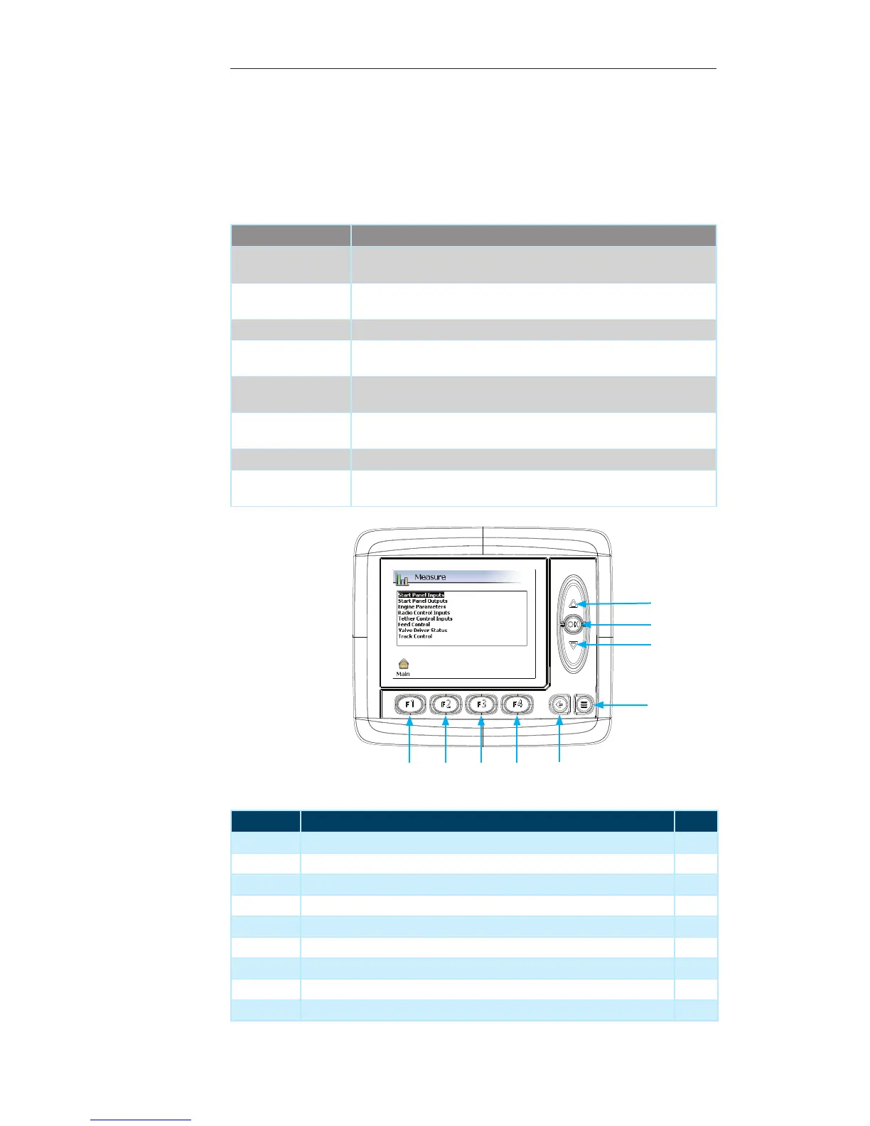
Display Module Navigation
Number Description Page
1 Up Arrow — Press to navigate through the list of measure groups --
2 OK Button — Press to select the desired measure group --
3 Down Arrow — Press to navigate through the list of measure groups --
4 Menu Button — Press to return to previous “Display Page” --
5 Escape Button — Press to return to the “Main” menu page 21
6 F4 Button — Not used on the current screen --
7 F3 Button — Not used on the current screen --
8 F2 Button — Not used on the current screen --
9 F1 Button — Press to navigate to the “Main” menu page 21
Measure
This page provides the ability to measure the performance of various parameters on the
Machine. To access the “Measure” menu:
Press the “F2” button while on the “Main” menu page.1.
Contained within this page:
Measure Group Description
Start Panel Inputs Provides information about the inputs coming from the Start Panel to the
Machine
Start Panel Outputs Provides information on the status of the various outputs coming from the
panel to the Machine
Engine Parameters Provides information about the status of the different Engine parameters
Radio Control Inputs Provides information about the various inputs coming from the Radio
Control to the Machine
Tether Remote Inputs Provides information about the various inputs coming from the Tether
Remote to the Machine
Feed Control Provides information on the status of the various aspects of the Machine’s
Feed System
Valve Driver Status Provides information on the status of the Valve Driver
Track Control Provides information on the status of the various Machine Track Control
Functions
1
3
2
4
5
6
7
8
9