19
SECTION 5 - INSTALLATION INSTRUCTIONS
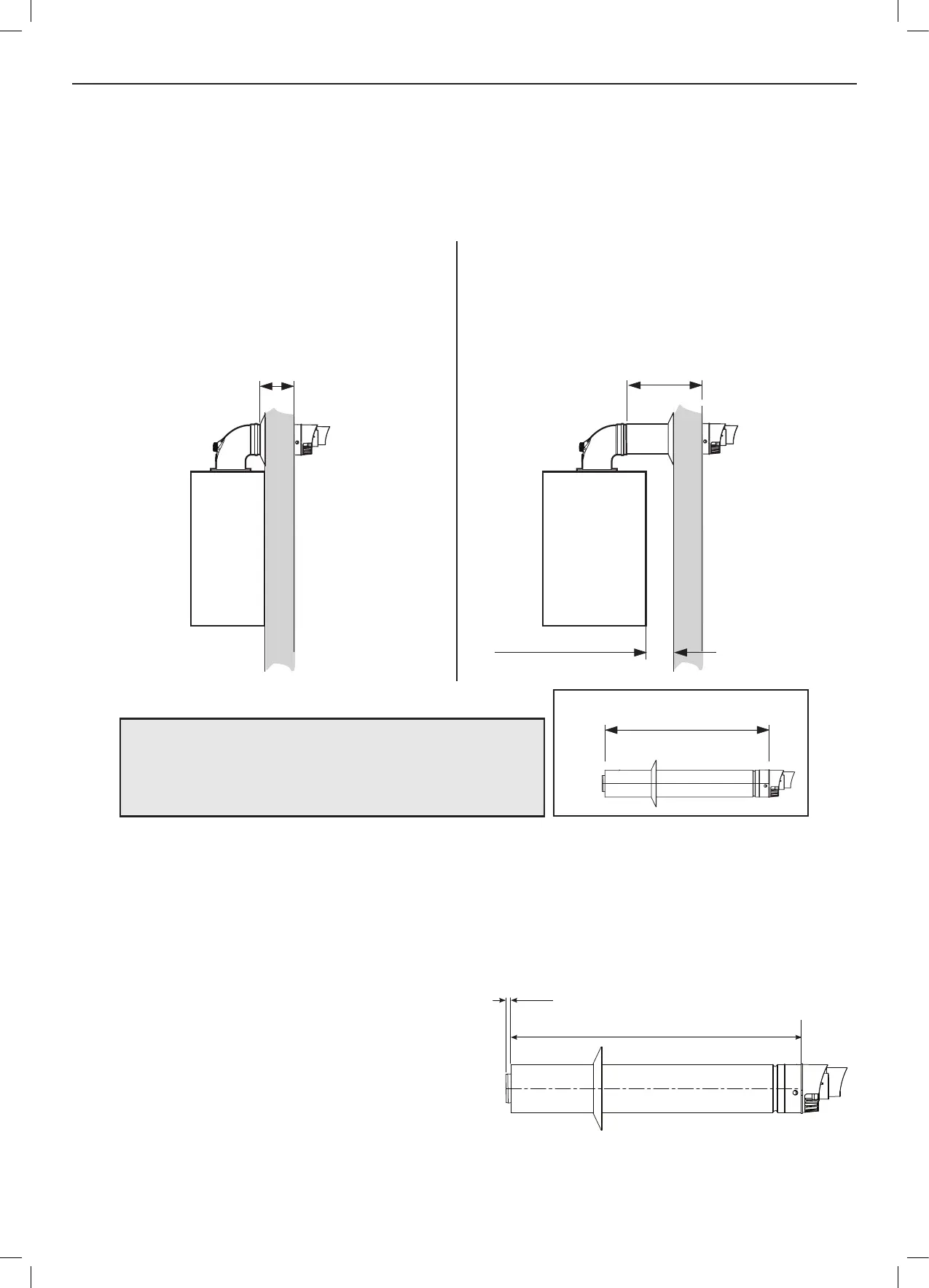
5.10 DETERMINING THE FLUE LENGTH
5.11 CUTTING HORIZONTAL FLUE TERMINAL RSF303 (600MM LONG)
10mm
Mark cut length =
A or B + 47mm from terminal lip
1. Measure from the outer terminal lip to end of outer ue. Mark the
required cut length (A or B + 47mm) around the circumference of the
outer ue and cut following the mark to ensure it is cut square.
2. Dress the cut end to make sure all burr’s are removed and the cut
edge is in its original shape.
3. Mark the inner tube 10mm longer than the outer tube around its
circumference and cut following the mark to make sure it is cut
square.
4. Remove all burrs and place a light chamfer on the outer edge to aid
assembly.
Centre of turret to edge of turret = 100mm
Turret has a ue insertion of 30mm
The white outer ue tube must protrude the wall by 17mm.
From centreline of turret to wall. Rear mount 155mm, side (including clearance) 200mm
NOTES
REAR
Fit
to wall
A
Flue length measured from outer terminal lip
to end of outer ue
A or B + 47mm
SIDE
Fit
to wall
B
Minimum clearance 2.5mm
WALL
WALL
FIGURE 1
REAR FLUE
Cut ue length = distance from edge of turret to outside of
wall dimension A + 47mm.
Note.MinimumdimensionAwhichcanbeaccommodatedis
91mm.
SIDE FLUE
Cut ue length = distance from edge of turret to outside of
wall dimension B + 47mm.
Note.MinimumdimensionBwhichcanbeaccommodatedis
136mm(withminimumclearanceof2.5mm).

 Loading...