20
SECTION 5 - INSTALLATION INSTRUCTIONS
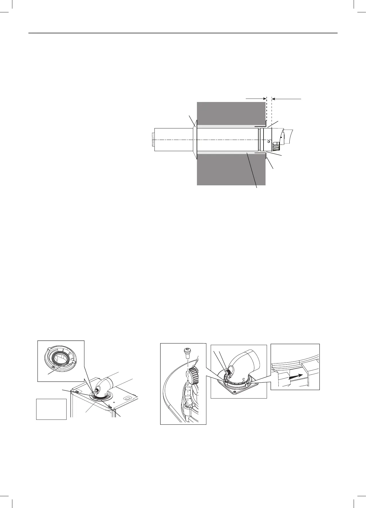
5.12 INSTALLING THE FLUE
FITTING FLUE THROUGH THE WALL
1. Ensure the seam and the outlet terminal are
at the top and tted as shown.
2. Once the ue is installed it is IMPORTANT
that the white air duct protrudes from the
aluminium ue collar (RSF 060) at least
17mm.
Note. If lessthan50%ofthelengthoftheueis
internaltheueshouldbettedfromoutside.
3. Fit the internal sealing ubber to the ue
(leave loose) and check protrusion externally
of the white air duct is 17mm.
4. Fit the turret as below
FITTING THE TURRET - Ensure the condensate trap / siphon is lled with water
1. Ensure the rubber seal is tted correctly on the appliance manifold and that all ue seals are undamaged.
2. Hold the ue rmly and push the turret on until it has travelled 30mm on to the ue pipe and is fully engaged. Make sure the
ue has not rotated or moved forward during tting and the ue seam is upper most.
3. Push the turret into the manifold ensuring the upper plastic lip is ush with the top of the manifold.
4. Fully engage the clamp location section into the manifold location holes. Rotate down on to turret ange.
5. Secure clamp to appliance using securing screw.
6. Ensure all sample points are accessible and all sample plugs and caps are tted.
7. Fully engage the ue into the turret and slide internal ubber to wall.
8. The gap between the aluminium ue collar (RSF 060) and the white air duct MUST be sealed with sealant to create a seal.
Flue Outlet
C
A
A - Duct Assembly
B - Flue Turret
C - Turret Clamp
D - Seal
Flue Outlet
D
B
Retaining
screw
Clamp Lugs
Sample points
WALL
Aluminium Flue
Collar (RSF 060)
Fill with
sealant
17mm min
Internal Sealing
Flubber
Fill with
sealant
5” hole
 Loading...