24
CONFIGURATION 1
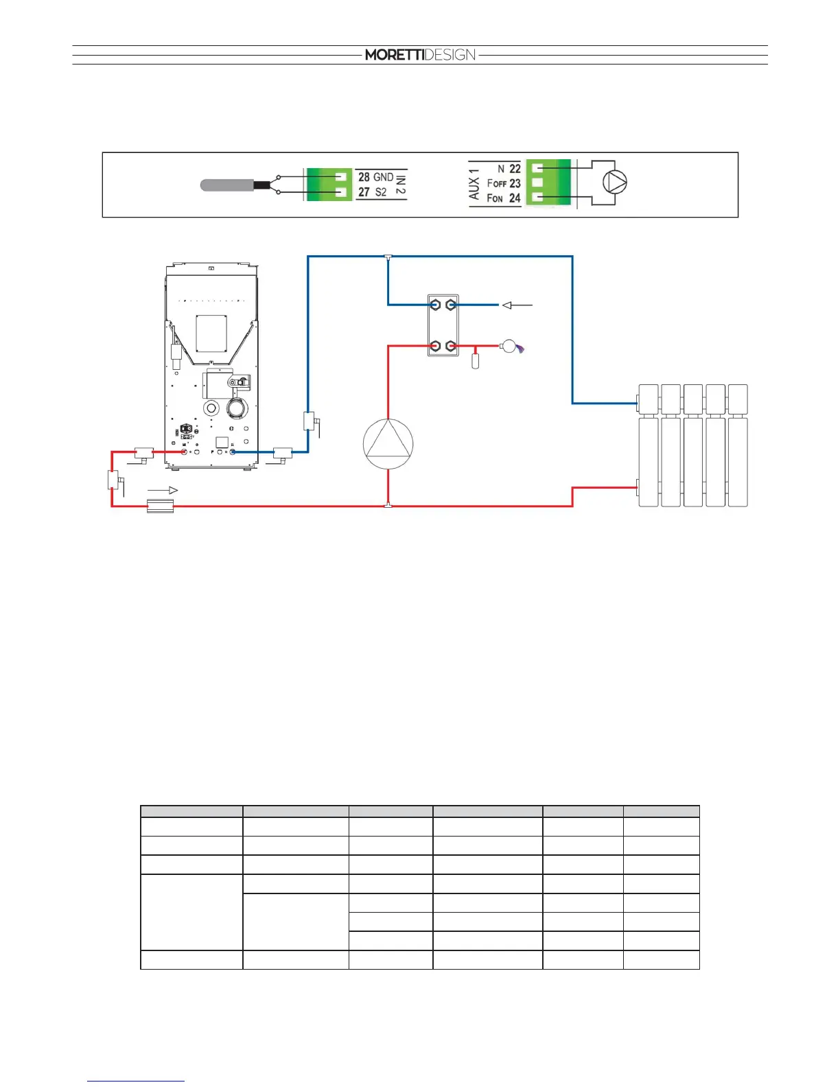
The configuration shown in the figure is set.
Connections on the control unit
Connections on the heating system (the following schematic is only illustrative)
The system includes: the hydro stove Boiler Probe (S1), the hydro stove Pump (P1), recirculation Pump (P2), Flow Switch (FL).
Set parameters on the hydro stove
T18 = 5°C, T19 = 53°C, T20 = 50°C, T21 = 80°C
Heating
• The Pump (P1) is activated above the pump activating thermostat T19.
• If there is a demand for domestic hot water the Pump (P1) is blocked.
• In Summer mode and working on Pellet, the Pump (P1) is activated when the water temperature exceeds the value of the thermostat T21.
• To prevent the water in the system from freezing, the Pump (P1) is activated when the water temperature drops below the thermostat T18.
• If the water temperature exceeds the value of the thermostat T21, for safety reasons the Pump (P1) remains always active.
Recirculation
• When there is a demand for domestic hot water and the water temperature in the hydro stove exceeds the value of the thermostat T19 or the
thermostat T20, the Pump (P2) is active.
• If the water temperature exceeds the value of the thermostat T21, for safety reasons the Pump (P2) is turned off.
System function:
TEMP. PROBE (S1) FLOW SWITCH (FL) MODE FUEL PUMP (P2) PUMP (P1)
T < 5°C
OFF
ON
5°C < T < 50°C
OFF OFF
50°C < T < 53°C
ON
OFF
50°C < T < 80°C
closed
ON
OFF
Wood OFF
ON
Winter
Pellet
OFF
ON
Summer
Pellet
OFF OFF
T > 80 °C
OFF
ON
open
S1
P1
sphere
valve
heat
exchanger
FL
domestic
cold water
domestic
hot water
heating system
P2
Pump (P2)
Flow Switch (FL)
non return
valve
sphere
valve
sphere
valve
sphere
valve