Instruction Manual
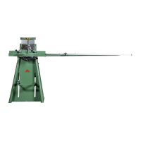
MORSØ Mitring Machine
Model F
40
Service F-4
Regulation of Draw Bar (Fig. F-4-1)
As the knives become worn it will be necessary to adjust the height of the draw bar (40).
The following procedure is adopted:
1. The foot pedal (34) is pressed down and locked by means of the height stop lock (41).
2. Loosen lock-nut (36).
3. The nut (37) is screwed upwards so that the edges of the knives go about 4 - 6 mm below
the upper side of the bottom knives.
4. Fasten lock-nut (36) against the draw bow (38).
Adjustment of Forward Travel (Fig. F-4-2)
When you have replaced the knives it might be necessary to adjust the forward travel to
ensure that the rear of the moulding is cut through (picture F-4-3).
1. The knife block unit is placed in the front most position with lever (13) (in the picture it is
shown in the rear position).
The fences (17) + (18) must be adjusted on standard (45°) position and be fastened.
2. Loosen lock-nut (14).
3. The offset bush (15) is turned with a spanner until the front point of the knives travels a
little bit beyond the fences (17) + (18), but the knives must not touch the fences.
4. Fasten nut (14) while holding the offset bush (15) in the adjusted position by means
of a spanner.
Moving the knife block down slowly check the position of the knives. If the fences (17) + (18)
are not touched, put a moulding in the machine and cut it. If the moulding does not split on
the foremost edge (i.e. the rear of the moulding) the adjustment is correct.