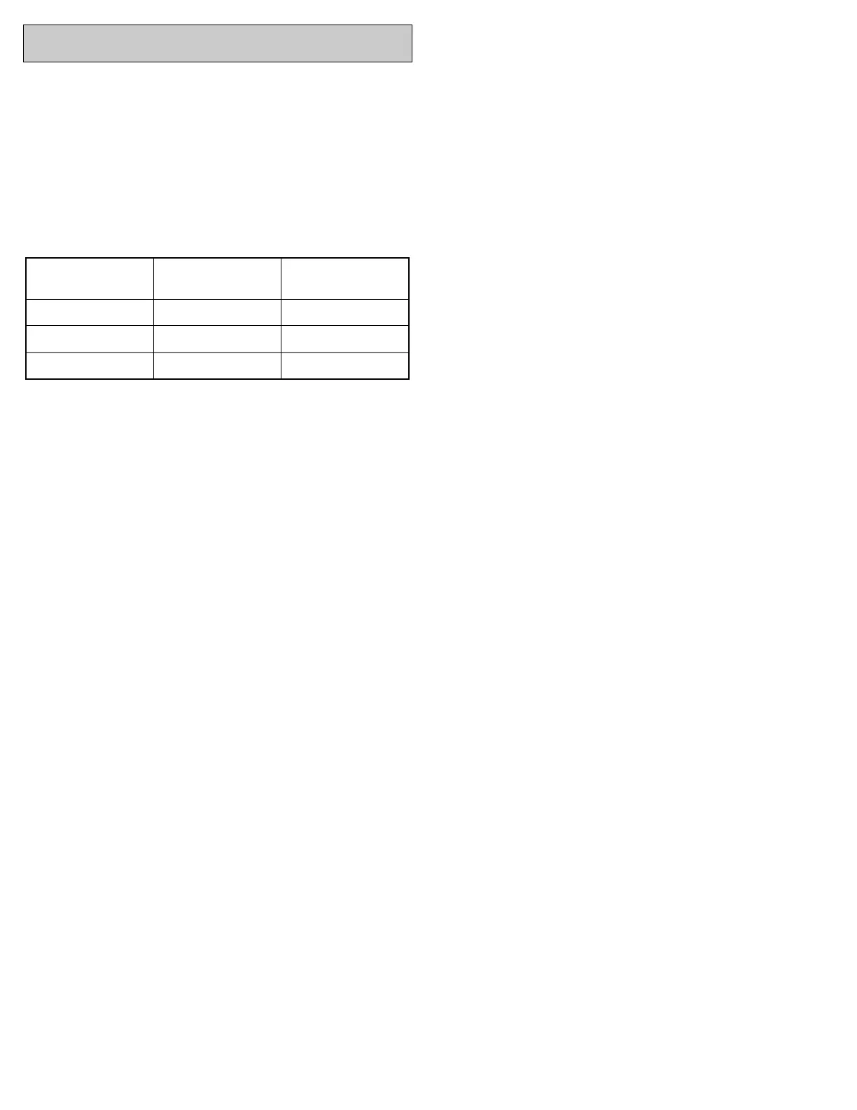
Thermostat Wire
Length
Thermostat Wire
Gauge
Thermostat Wire
Maximum Current
Feet/Meters AWG Amps
0-70/21.34 20 3.00
0-112/34.14 18 3.00
MORTEX PRODUCTS INC. 501 TERMINAL RD FORT WORTH, TX 76106 Page 14
Table 9: Low Voltage Wire Gauge
and Maximum Lengths
Thermostat Wiring
Thermostat wires must on the right side of the furnace cabinet
and must be no smaller than 20 AWG. Refer to Table 9 for
recommended wire gauge, lengths and maximum current for
each wire gauge.
NOTE: The thermostat wire cable must enter only on the left side
of the furnace cabinet into the left side of the control box through
the provided plastic bushing and CANNOT pass through the line
voltage section (right side) of the control box.
NOTE: A 3 Amp slow-blow fuse is located on the left side of the
control box that protects the 24 VAC circuit. Replace this fuse only
with the equivalent 3 Amp glass fuse.
The use of a five-conductor cable from the thermostat to the
furnace is recommended for typical heating or heating/ cooling
installations with a two or three-conductor cable from the furnace
to the cooling-only outdoor unit.
A seven or eight conductor cable from the thermostat to the
furnace is recommended for a typical heat pump installation
with a five-conductor cable from the furnace to the heat pump
outdoor unit.
The thermostat wire colors for typical heating, cooling and heat
pump connections are shown in Tables 10 and 11.
Thermostat Installation
The thermostat should be located on an inside wall in an open
area to more closely regulate average room air, preferably where
there is air movement back to air handler. Locating height of
thermostat is important. If possible, the thermostat should be
located in a hallway upstream from the air handler return airflow,
not within 3 feet of from any windows and 52 to 66 inches above
the floor. DO NOT place the thermostat within three feet of any of
the air-distribution supply air registers.
Maintenance, operating and/ or programming instructions are in
the envelope accompanying the thermostat. Give the envelope to
the homeowner.
SECTION 9: THERMOSTAT WIRING AND LOW
VOLTAGE CONNECTIONS


 To Next Page