1
2
3
4
5
C
L
G
N
MORTEX PRODUCTS INC. 501 TERMINAL RD FORT WORTH, TX 76106 Page 19
SECTION 10: BLOWER MOTOR SPEED TAP SELECTION
To avoid personal injury or property damage, make
certain that the motor leads cannot come into contact
with non-insulated metal components of the unit.
Be sure to disconnect the electrical power supply to the
furnace by turning o the circuit breakers for the furnace
in the home’s main electrical panel (circuit breaker box)
and the circuit breaker(s) in the furnace control box
before removing the furnace front access panel and
control box cover.
1. Switch the circuit breakers for the furnace in the main electrical
panel (circuit breaker box) to the “OFF” position and switch the
furnace circuit breaker(s) to the “OFF” position.
2. Remove the furnace front access panel.
3. Remove the control box cover.
4. Disconnect the speed tap wire to be changed from the ¼ in
(6.35 mm) spade terminal on the back of the LVTB and connect
the desired speed tap wire to that spade terminal. Refer to Table
12 for motor speed tap descriptions, Table 14 for factory speed
tap settings, and the furnace wiring diagram for speed tap wire
colors.
5. Reinstall the control box cover.
6. Reinstall the front access panel.
7. Switch the furnace circuit breaker(s) to the “ON” position.
8. Switch the circuit breakers for the furnace in the main electrical
panel to the “ON” position.
Speed Tap 5: High Speed – Cooling or Heat Pump
Heating Modes
Speed Tap 4: Med-High Speed – Cooling or Heat Pump
Heating Modes
Speed Tap 3: Medium Speed – Cooling or Electric Resistance
Heating Modes
Speed Tap 2: Med-Low Speed – Electric Resistance
Heating Mode
Speed Tap 1: Low Speed – Constant Circulation Mode Only
NOTE: DO NOT USE SPEED TAP 1 FOR HEATING OR COOLING
MODES! Speed Tap 1 airflow is approximately 200 CFM. This
is not enough airflow for electric heating, cooling, or heat
pump heating operation. If Speed Tap 1 is used for cooling, the
evaporator will freeze up. If Speed Tap 1 is used for heat pump
heating, the outdoor unit high pressure switch will trip. If Speed
Tap 1 is used for electric resistance heating, the heater over
temperature limits will cycle.
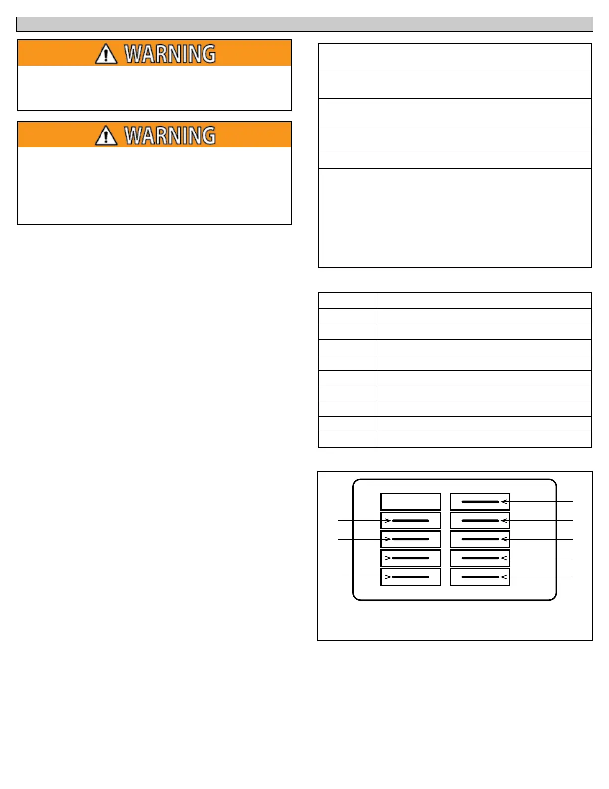
Table 12: Constant Torque Motor Speed Tap Descriptions
Table 13: Constant Torque Motor Terminal Descriptions
Figure 24: Constant Torque Motor Terminals
Terminal Connection
C Speed Tap Common - 24 VAC Common
L Supply Voltage - 240 VAC Line 1
G Ground Connection
N Supply Voltage - 240 VAC Line 2
1 Low Speed Tap - 24 VAC Input
2 Medium-Low Speed Tap - 24 VAC Input
3 Medium Speed Tap - 24 VAC Input
4 Medium-High Speed Tap - 24 VAC Input
5 High Speed Tap - 24 VAC Input



 To Next Page