MORTEX PRODUCTS INC. 501 TERMINAL RD FORT WORTH, TX 76106 Page 28
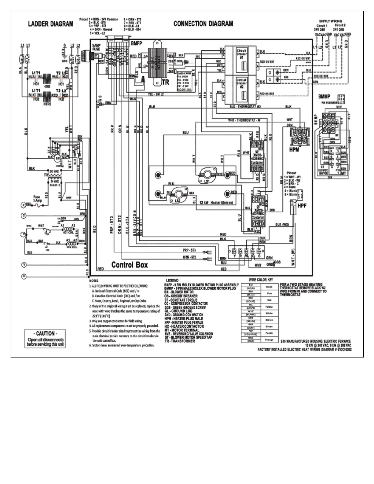
Figure 27: 12 kW Electric Heat Wiring Diagram
NOTE: IF ANY OF THE ORIGINAL WIRE SUPPLIED WITH THIS UNIT MUST BE REPLACED. IT MUST BE REPLACED WITH TYPE 105°C
THERMOPLASTIC OR ITS EQUIVALENT.
BLOWER MOTOR SPEED TAP INFORMATION:
TAP 5 – High Speed – Used for cooling operation. Energized by the “Y” thermostat terminal.
TAP 4 – Med-High Speed – Used for cooling or heating operation. Energized by the “Y” or “W” thermostat terminals. TAP 3 – Medium Speed
– Used for cooling or heating operation. Energized by the “Y” or “W” thermostat terminals. TAP 2 – Med-Low Speed – Used for heating
operation only. Energized by the “W” thermostat terminal. TAP 1 – Low Speed – Used for constant circulation operation ONLY. This speed
tap only delivers approximately 200 CFM which is insuffient to support cooling or heating operation and will result in the indoor coil
freezing and tripping of the heating limits. Energized by the “G” thermostat terminal.
WARNING – LOW SPEED TAP IS TO BE USED FOR CONSTANT CIRCULATION ONLY!