SECTION 5: DOWNFLOW FURNACE INSTALLATION
MORTEX PRODUCTS INC. 501 TERMINAL RD FORT WORTH, TX 76106 Page 6
Installing Downflow Furnace and Return Air Grille Frame
Assembly in Alcove
The Return Air Grille kit is approved for use in an alcove for a
heating only installation without an air-conditioning coil. The
return air grille frame assembly is available in 18” (457.2mm)
height and 24” (609.6mm) height. Follow the steps below to
install the return air grille frame assembly to the furnace.
1. Before installing the return air grille frame on the furnace,
confirm there is enough clearance to install the furnace and
the return air grille assembly.
2. Holes for the electrical and thermostat wiring must be cut
prior to installing the furnace and return air grille.
3. Remove the stretch wrap, top and bottom shipping covers,
and corner posts from the furnace.
4. Remove the furnace front access panel.
5. Remove the return air grille frame assembly from its carton.
6. Set the return air grille frame assembly on the front of the
furnace top cover as shown in Figure 6. Line up the screw
holes in the frame assembly with the screw holes in the
furnace top cover and attach the frame assembly to the
furnace top cover using the provided screws.
7. Slide the furnace onto the floor base. Push the furnace back
until the furnace cabinet is against the rear flange of the floor
base.
8. Secure the furnace cabinet to the floor by drilling two holes
through the furnace base and the floor base in the right and
left front inside corners of the furnace cabinet. Use two screws
to secure the furnace and floor base to the floor.
9. Place the air filter in the filter rack in the louvered door and
install the louvered door on the frame assembly by inserting
the tabs in the bottom of the louvered door into the slots in
the furnace top cover.
10. Secure the louvered door to the frame assembly with the
thumb screw in the top of the door.
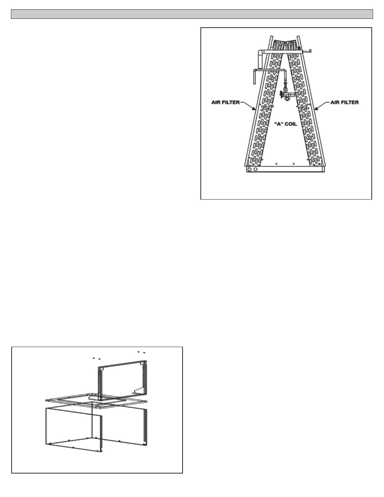
Downflow “A” Coil Return Air Filter Rack Assembly For Alcove
or Closet Installations
An air filter assembly is available that attaches to the “A” coil as
shown in Figure 7. This assembly utilizes 2 filters, one for each coil
slab. A return air grille with a sufficient free area opening must be
installed in the closet door or wall of the closet.
Installing the Downflow Furnace and Coil Cabinet in Alcove
and Closet
The downflow coil cabinets are approved for use in an alcove
or closet installations with an approved air conditioning coil.
The downflow coil cabinets are available in 23.25in (590.55mm),
30.50in (774.7mm) and 41.25in (1,047.75mm) height. The furnace
is 33in (838.2mm) in height making the combined furnace and
coil cabinet height 56in (1,422.4mm), 63in (1,600.2mm) and 73in
(1,854.2mm). Follow the steps below to install the coil cabinet
assembly to the furnace.
1. Before installing the coil cabinet on the furnace, confirm there
is enough clearance to install the furnace and the coil cabinet
assembly.
2. Holes for the refrigerant tubing, condensate drain line, line
voltage supply wiring, thermostat wiring, and outdoor unit
control wiring must be cut prior to installing the furnace and
coil cabinet.
3. Remove the stretch wrap, top and bottom shipping covers, and
corner posts from the furnace.
4. Remove the furnace front access panel and lay the furnace on
its back.
5. Remove the coil cabinet from its carton and assemble it per the
instructions.
6. Lay the coil cabinet on its back and place the coil cabinet
flanges against the furnace top cover.
7. Secure the cooling coil cabinet to the top cover of the furnace
using the provided screws.
8. Slide the furnace onto the floor base. Push the furnace back
until the furnace cabinet is against the rear flange of the floor
base.
9. Drill two holes through the furnace base and the floor base at
the right and left front inside corners of the cabinet. Use two
screws to secure the furnace and floor base to the floor.
Figure 7: Downflow “A” Coil Return Air Filter Location
Figure 6: Return Air Grille Frame Assembly