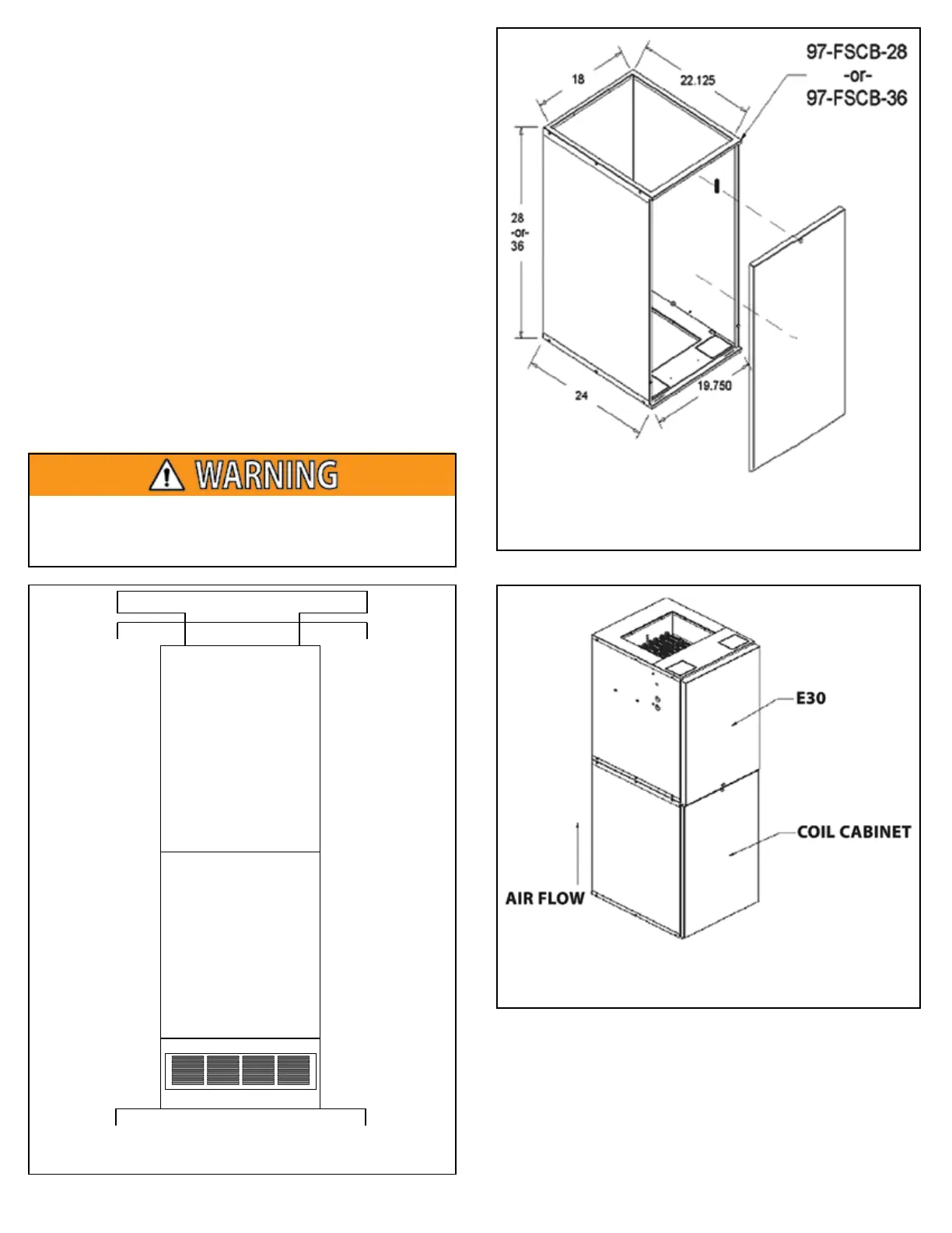
E-30
ELECTRIC FURNACE
UPFLOW COOLING
COIL CABINET
RETURN AIR BOX
RETURN AIR FILTER GRILLE
COIL CABINET DOOR WILL
NOT HAVE LOUVERS
FLOOR
CEILING SUPPLY DUCT
SUPPLY DUCT IN ATTIC
MORTEX PRODUCTS INC. 501 TERMINAL RD FORT WORTH, TX 76106 Page 9
8. The installer must fabricate a duct connector that mounts
below the coil cabinet for a return duct connected to a remote
return air grille. The duct connector must allow for the
refrigerant line set to be in front of the duct connector
plenum.
9. Position the furnace on the top of the coil cabinet as shown in
Figure 14 with the air discharge pointing upward and secure it
to the coil cabinet with the at least 4 field supplied screws.
10. Use the upflow duct connector kit to attach the furnace to the
overhead supply duct.
11. Stand the assembled furnace, coil cabinet, and return air
cabinet up and seal all of the joints with mastic or tape.
12. Insulate the inside of the coil cabinet and the inside of the
solid front door with a minimum 1/2 in (12.7 mm) thick
insulation to prevent condensation from forming on the
outside of the coil cabinet when the system is operating in the
cooling mode.
13. Slide the furnace into position below the supply air duct
and secure the return air cabinet to the floor with at least 4
field supplied screws.
14. Use the duct collar to secure the supply air duct to the top of
the furnace.
When installing the duct collar, do not drive pointed screws
into the control box and make sure no screws are touching
any components or wires.
Figure 12: Typical Upflow Installation
Figure 13: Upflow Coil Cabinet
Figure 14: Upflow Furnace and Coil Cabinet