SECTION 7: UPFLOW COIL CABINET AND RETURN AIR CABI-
NET INSTALLATION
MORTEX PRODUCTS INC. 501 TERMINAL RD FORT WORTH, TX 76106 Page 8
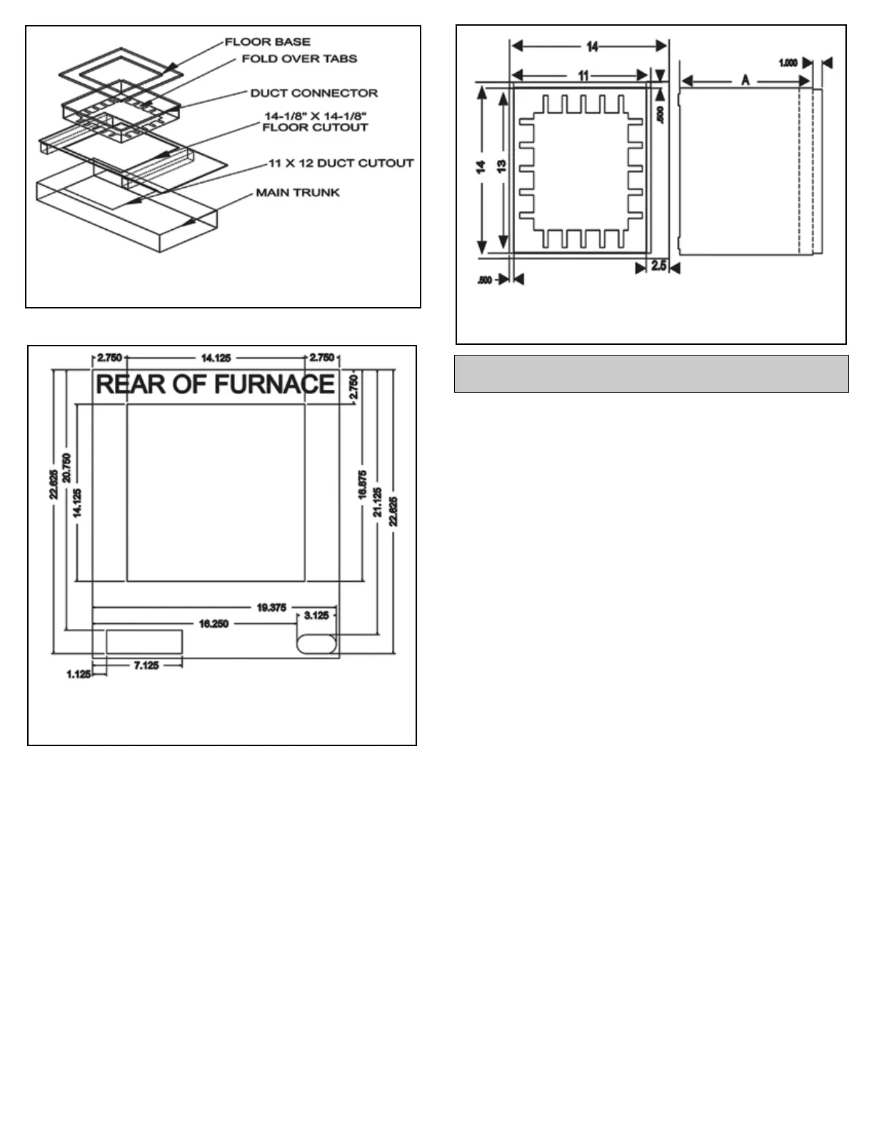
Figure 9: Duct Connector and Combustible Floor Base
Figure 11: Duct Connector Dimensions
Figure 10: Combustible Floor Base Dimensions
Upflow coil and return air cabinets are approved for use in alcove
or closet installations with an approved air-conditioning coil.
Upflow coil cabinets are available in 28” (711.2 mm) and 36”
(914.4 mm) heights. The return air cabinet height for applications
with a 28” (711.2 mm) tall coil cabinet is 20” (508mm) and 24”
(609.6 mm) for applications with a 36” (915.4 mm) tall coil cabinet.
The total height of the furnace, coil cabinet and return air cabinet
is as follows:
Return Air Cabinet Height = 20” (508 mm)
Coil Cabinet Height = 28” (711.2 mm)
Furnace height = 33” (838 mm):
Total Height = 81” (2,057.4 mm)
Return Air Cabinet Height = 24” (609.6 mm)
Coil Cabinet Height = 36” (914.4 mm)
Furnace Height = 33” (838 mm)
Total height = 93” (2,362.2 mm)
Follow the steps below to install the coil cabinet assembly.
1. Before beginning the installation, confirm there is enough
clearance to install the furnace, coil cabinet, and return air
cabinet.
2. Holes for the refrigerant tubing, condensate drain line, line
voltage supply wiring, thermostat wiring, and outdoor unit
control wiring must be cut prior to installing the furnace, coil
cabinet, and return air cabinet.
3. Remove the stretch wrap, top and bottom shipping covers, and
corner posts from the furnace.
4. Remove the furnace front access panel (door) and lay the
furnace on its back.
5. Remove the coil and return air cabinets from their cartons.
6. If required, remove the left or right metal knockout (not both)
in the bottom of the coil cabinet so the refrigerant lines and
condensate drain line can be routed through it. Refer to Figure
13 for location of the metal knockouts.
7. Position the coil cabinet on top of the return air cabinet and
secure it to the return air cabinet with at least 4 field supplied
screws.