G
W
Y
C
R
THERMOSTAT
G
W
W2
Y
C
R
FURNACE
Y
C
COOLING
OUTDOOR SECTION
RH
G
C
Y
Y
RC
THERMOSTAT
R
G
W1W
C
C
FURNACE
COOLING UNIT
OUTDOOR SECTION
W2W2
MORTEX PRODUCTS INC. 501 TERMINAL RD FORT WORTH, TX 76106 Page 16
Typical Heat Pump Low Voltage Wiring Connections
1. Remove the front access panel.
2. Remove the control box cover.
3. Install a field supplied grommet in the 3/8” hole on the right
side of the furnace cabinet to protect the thermostat wire
cable(s).
4. Strip ½” of the insulation from the end of each wire in the low
voltage cable(s).
5. Insert the wire cable(s) from the thermostat and outdoor unit
through the grommet in the right side of the furnace cabinet
and through the 3/8” strain relief installed in the control box.
6. Place the thermostat wire cable next to the furnace low
voltage terminal block (LVTB).
7. Connect the RED wire (24 VAC) from the thermostat “R”
terminal and the RED wire from the “R” terminal on the
outdoor unit control board to the “R” screw terminal on the
LVTB.
8. Connect the WHITE wire (emergency heat) from the
thermostat “W/E” terminal to the “W” screw terminal on the
LVTB.
9. Furnaces with 2-Stage Heat (12kW – 20kW Only): Remove the
BLACK/W2 wire (2nd stage heat) connected to the spade
terminal on the back of the furnace LVTB “W” terminal, cut
the terminal off, and strip ½” of the insulation from the end of
the wire. Connect this wire to the BLACK wire from the
thermostat W2 terminal with a wire nut.
10. Connect the GREEN wire (indoor fan) from the thermostat “G”
terminal to the “G” screw terminal on the LVTB.
11. Connect the YELLOW wire (cool/heat pump heat) from
the thermostat “Y” terminal and the YELLOW wire from the
“Y” terminal on the outdoor unit control board to the “Y” screw
terminal on the LVTB.
12. Connect BROWN wire (24 VAC common) from the thermostat
“C” terminal and the BROWN wire from the “C” terminal on the
outdoor unit control board to the “C” screw terminal on the
LVTB.
13. Connect the ORANGE or BLUE thermostat wire from the
thermostat “O” or “B” terminal to the ORANGE or BLUE
(reversing valve solenoid) wire from the “O” or “B” terminal
on the outdoor unit with a wire nut. The connections (“O” vs.
“B”) will depend on the outdoor unit brand. Refer to the
outdoor unit installation instructions and wiring diagram
before making this connection.
14. If the outdoor unit control board has a terminal for energizing
electric heat during the defrost cycle and this feature is
desired, connect a wire from that terminal to the “W1” terminal
on the LVTB. Refer to the outdoor unit installation manual and
wiring diagram for more information.
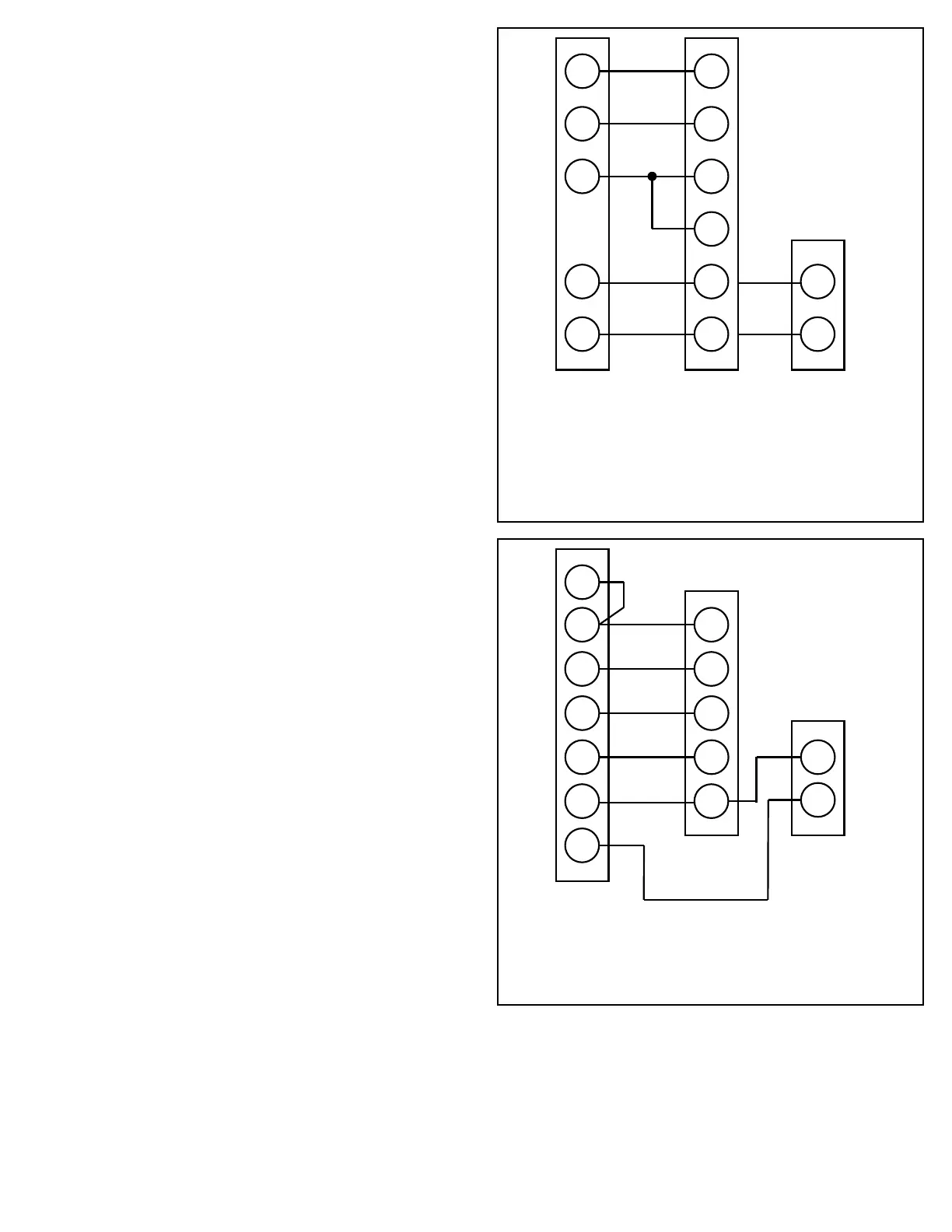
Figure 18: Typical Single-Stage Heat and
Cool Low Voltage Connections With Single
Transformer in Furnacees
Figure 19: Typical Two-Stage Heat/Single-Stage
Cool Low Voltage Connections With Single
Transformer in Furnace


 To Next Page