Morton
®
System Saver
®
Installation & Operation Manual 9
Installation Instructions
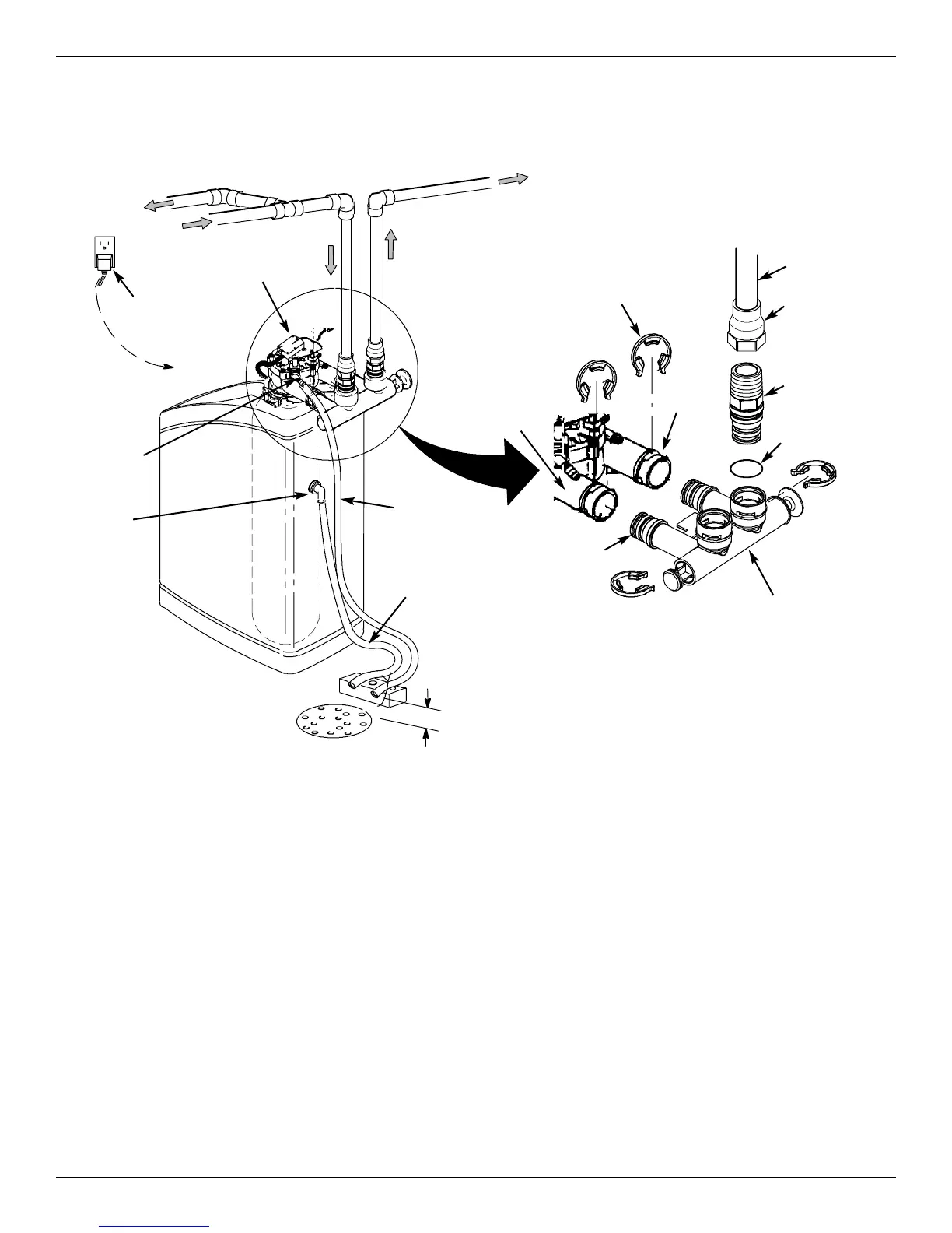
Typical Installation
FIG. 10
Inlet
Outlet
Clips
Pipe
To Outside
Faucets
1” NPT Sweat
Adaptor (not
included)
O-ring
Single Bypass Valve
Lubricated
O-ring
Conditioned
Water
Hard Water
Main Water Pipe
Plug-in
Transformer
Water Softener
Valve
To
Controller
Valve Drain
Elbow
Valve Drain
Hose*
*Do not connect
the water softener
valve drain tubing
to the salt storage
tank overflow
hose.
Floor Drain
Overflow
Drain
Elbow
Salt Storage
Tank Overflow
Hose*
Secure Valve Drain
Hose in place over
Floor Drain
NOTE: See “Air Gap Requirements” section.
NOTE: Water Softener shown with Salt Hole
Cover and Top Cover removed
1” NPT
Threaded
Adaptor
1-1/2”
air gap
Step 1. Turn Off Water Supply
1. Close the main water supply valve, located near the
well pump or water meter.
2. Shut off the electric or fuel supply to the water
heater.
3. Open all faucets to drain all water from house pipes.
NOTE: Be sure not to drain water from the water
heater, as damage to the water heater ele-
ments could result.
Step 2. Assembly
1. Morton
®
System Saver
®
models are factory assem-
bled. During installation, remove the Salt Hole
Cover and set it aside to prevent damage. Check
the brinewell to be sure it is secured and vertical
(See Figure 11). Slide Faceplate Cover forward to
expose back valve assembly.
2. Lift the brine valve out of the brinewell. Make sure
the float stem is parallel to the stand tube so the
seals will seat properly during operation. Place the
brine valve back into the bottom of the brinewell and
reinstall the brinewell cover.
continued on next page