MoTeC Installation 11
Connecting Devices Examples
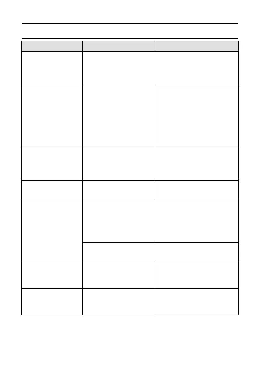
Device Connect via Remarks
Sensors
Inputs:
The appropriate input
type depends on the
sensor type
MoTeC supplies datasheets
with wiring details for all
sensors via the website
External Buttons for:
- Display mode
- Display next line
(and optional
previous line)
- Alarm acknowledge
- Lap number reset
- etc.
Inputs:
Digital or Speed inputs
Wire between Dash Logger
input and Dash Logger 0 V.
If wired to an Analogue
Voltage input connect an
external pull-up resistor
between the input pin and the
5 V sensor supply.
External LED Lights
Outputs:
Auxiliary output
Wire between one of the
Auxiliary Outputs and battery
positive and include a current
limiting resistor
SLM Shift Light
Module
Communications:
CAN
K-type
Thermocouples
Inputs:
Analogue Voltage or
Analogue Temperature
input
Connect via TCA (Thermo
Couple Amplifier)
Communications:
CAN
Connect via E888
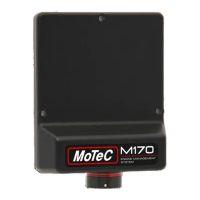
ECU M4, M48, M8
Communications:
RS232
Uses the Telemetry feature of
the ECU to send data to the
Dash Logger
ECU 'hundred
series': M400, M600,
M800, M880
Communications:
CAN
Ensure the ECU and Dash
Logger are connected on the
same CAN bus
 Loading...