03. CONFIGURATION
EXTENDED MENU 3 CAPACITORS CONNECTION SCHEME
04. COMPONENT TEST
This test only applies to 110/230V motors. To test a 24V motor, just connect
the motor cables to a 24V battery.
If you need to restore control board to the factory setting, press the SEL and SET but-
tons simultaneously. All LEDs will light up temporarily, and when erased, the success
of the operation is confirmed.
The control board is prepared to a safety device connection in accordance with the sec-
tion 5.1.1.6 of standard EN 12453. In every maneuver is performed a test for the Security
Device and the Lock. In case of a function/connection failure the motor doesn’t start
and every LED’s remain in a intermittent mode, indicating the error. When the photoce-
lls operation is corrected, the control board returns to it’s normal functioning. This ac-
tion by the control board allows to recognize failures in accordance with is mentioned
in category 2 of EN 954-1.
In the position corresponding to each transmitter input in low voltage, the control
board has a LED to identify the condition of it. The LED ON indicates that the input is
closed, while the LED OFF indicates that the input is open.
• PHOTOCELLS TEST
• TRANSMITTER'S TEST
PHOTOCELLS AND CONTROLS TEST
RESET TO CONTROL BOARD
Motor power programming during the deceleration:
It is possible to choose up to 6 different levels, relatively the force that the motor per-
forms in deceleration. The levels are represented by combinations of the LED indicated
in the table above.
Scroll through the LEDs with the SEL button to set the desired power, knowing that the
LED AUT / P-P. ON corresponds to minimum power, while the LEDs AUT / P-P., CODE,
CODE PED, INB. CMD. AP, T. MOT., T. MOT. PED ON correspond to maximum power.
The control board is supplied by the manufacturer with the power regulated at level 3
(AUT / P-P., CODE, CODE PED ON).
AUTOMATISM
8μF
Capacitor
1
2
3
2
COM 1
COM 2
COM
Ground Wire
Phase 2
Phase 1
Open
Close
Motor
Power Supply 1
Power Supply 2
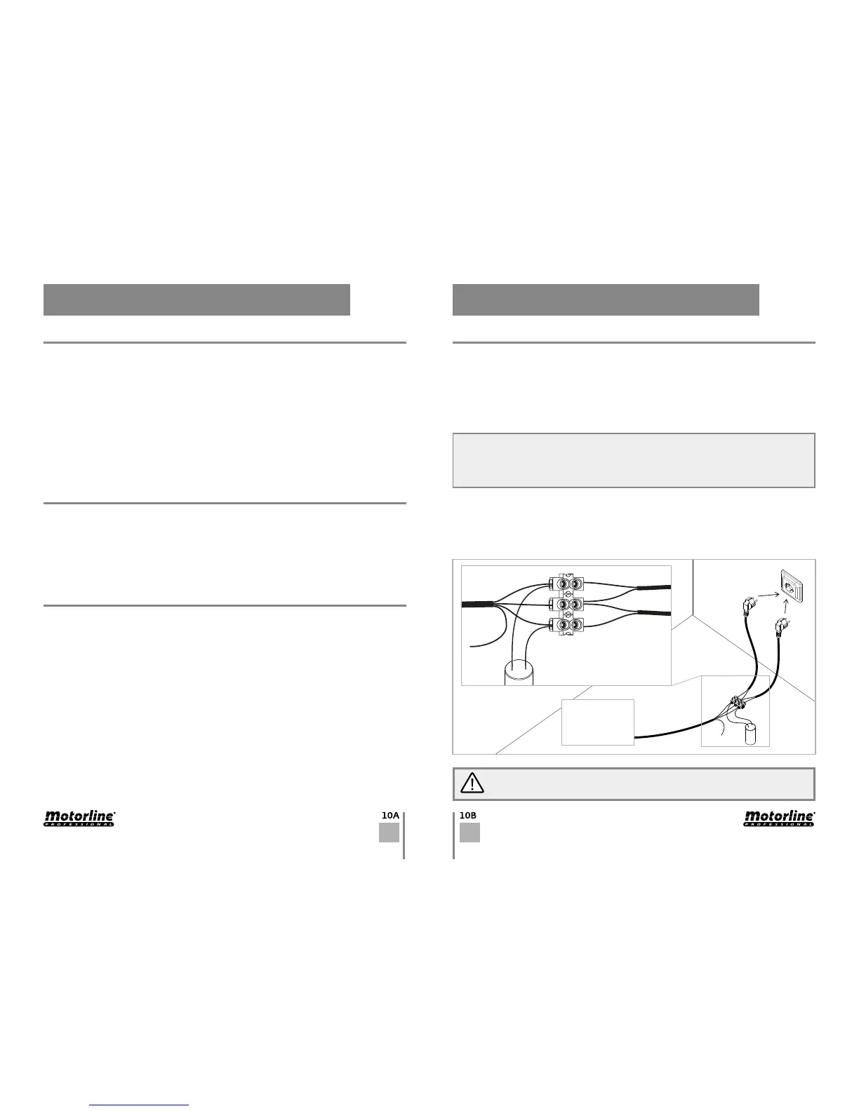
To detect if the malfunction is on the control board or on the motor is, sometimes,
necessary to perform tests with connection directly to a 110/230V power supply.
For this, it is necessary to interpose a capacitor on the connection in order to the
automatism to work (check the type of capacitor to be used in the product manual).
The diagram below, shows how to make that connection and how to merge the different
components wires.
01 • Connect the power wires to the terminal, as shown below.
02 • Connect the automatism wires in the terminal, interposing a capacitor in the
opening and closing wires.
03 • Once these connections are completed, connect to a 110/230V power outlet,
depending on the motor/control board in test.
NOTES:
> To perform the tests, there is no need to remove the automatism from the place it is instal-
led, because in this way, it is possible to understand if the automatism can function properly
connected directly to the current.
> You should use a new capacitor during this test to ensure that the problem does not lie on it.