EasyManuals Logo

Motorline MC2 User Manual

Motorline MC2
13 pages
To Previous Page IconTo Previous Page
Page #13 background imageLoading...
Page #13 background image
13
V
PUL
SERR.
PED
L N
LAMP
230V
MOTORE 1
AP COM CH
MOTORE 2
AP COM CH
PUL PED DS1 DS2
~ ~~ ~
0V
12/24V
0V NC
COM
12/24V
1 32 4 5
1 2
SEL SET
T.RIT.ANT
T. PAUSA
T.MOT.PED
T.MOTOR
INB.CMD.AP
CODE PED
CODE
AUT/P-P
1D
1D
DS S2
1 1 12 2 23 3 34 45 56 67 78 89 9 1110 10 12
0V NCCOM
12/24V
1
-
3
COM
K1 K2
2
+
4
NC
5
NO
0V
12/24V
1
-
2
+
0V NCCOM
12/24V
1
-
3
COM
K1 K2
2
+
4
NC
5
NO
0V
12/24V
1
-
2
+
PT
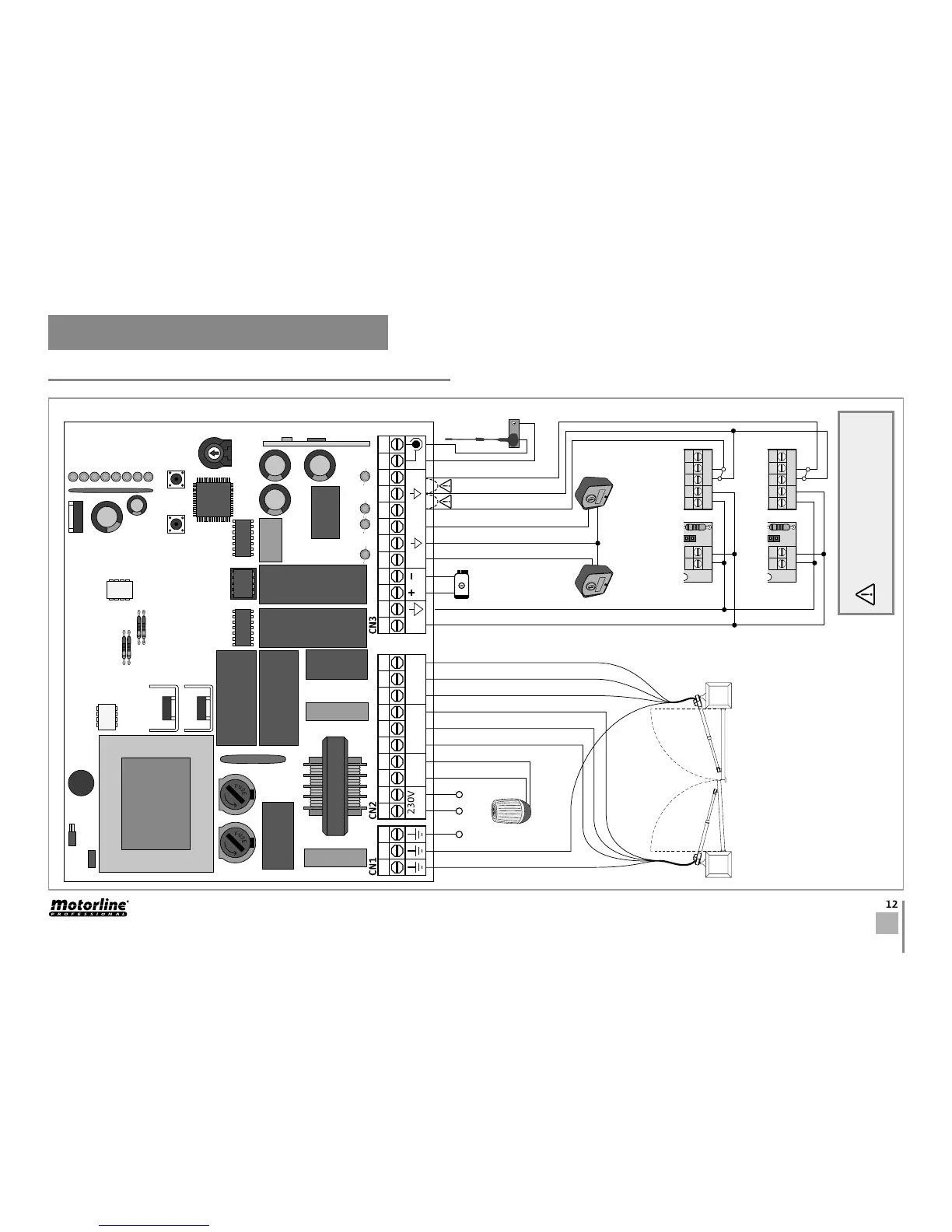
06. CONNECTION SCHEME
COMPONENT'S CONNECTION TO THE CONTROL BOARD
If you don't use photocells it's
necessary the application of shunts.
PL L N
Interior Photocells
Exterior Photocells
- Motor 1 starts opening before Motor 2 -
- Motor 2 starts closing before Motor 1
- A capacitor must be intercalated in each
motor. Please, consult the product's
manual to check the capacity and how to
connect it.
NOTE • If any one of the motors move in
the wrong way, just switch the brown and
black cables of that motor to change the
direction.
Complete
Opening (2
doors)
Lock
Light Bulb
Antenna
Earth wire
Black
Brown
Earth wire
Blue
Blue
Brown
Black
Pedestrian
Opening (1
door)
Motor 1
Motor 2
- Force +

Other manuals for Motorline MC2

Questions and Answers:

Question and Answer IconNeed help?

Do you have a question about the Motorline MC2 and is the answer not in the manual?

Motorline MC2 Specifications

General IconGeneral
BrandMotorline
ModelMC2
CategoryControl Unit
LanguageEnglish

Related product manuals