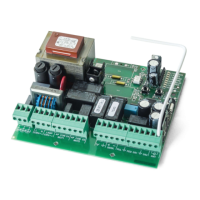
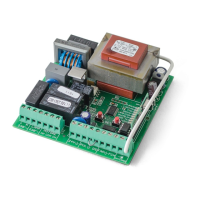
02. THE CONTROL BOARD 02. THE CONTROL BOARD
PROGRAMMING PRE-RECOMENDATIONS PROGRAMMING PRE-RECOMENDATIONS
• POWER AND SPEED OF MOTORS
The control board has a trimmer VR1 to adjust the force and speed of the
motors controlled by the microprocessor. The adjustment can be effec-
ted between 50% and 100% the power.
At each start-up movement, the control board applies the maximum
power during 2 seconds, even when it is made regulating force to a value
than not the maximum.
FORZA
When you adjust the trimmer VR1 has to remake course programming, as they
could varied the times of maneuvering and deceleration.
+
-
• PROGRAMMING THE CONTROL BOARD - BUTTONS SEL/SET
SEL button: It makes the selection of the function to change. The se-
lection is identified by the flashing of the LED corresponding to the
selected function at that time.
Pressing the SEL button repeatedly will cycle through the various
functions to be programmed. The selection remains active for 10 se-
conds, after these time the control board returns to original status
(no active selection).
SET button: Makes programming the selected function through the
SEL button.
The SET button may be substituted by a remote control from the latter is pro-
grammed.
SETSEL
• OPERATION OF LIGHTBULB
The operation of the output is conditioned by the mo-
vement of the motor and automatic closing. When the
automatic closing is activated, the 110/230V output is
activated even during pause time.
3 4
• OPERATION WITH TIMER
Instead of a opening / closing (PUL) push button, the
control board can be operated with a TIMER. With a
TIMER connected to the control board it is possible to
program an exact time for the motor to perform both
the opening and the closing, in automatic mode.
5 6
CN3
CN2
Lightbulb:
03 and 04 • This output allows connection of a lightbulb (see page 4B).
Capacitor:
05 and 07 • Connect the capacitor between the outputs 05 and 07.
08 and 10 • Connect the capacitor between the outputs 08 and 10.
Electric lock:
03 and 04 • This output allows connection of an electric lock (see pág.9A)
Push button / selector:
05 •
Allows connection the push-button / selector to full opening (NA).
06 • Allows connection the push-button / selector to full opening (NA).
Safety circuits:
08 • This circuit allows the connection of all types of safety devices such as
photocells, safety edge, etc.
This device operates only in the gate closing maneuver and, when activated, it
reverses the direction of the automatism.
10 • This circuit allows the connection of all types of safety devices such as
photocells, safety edge, etc.
This device operates in the opening and closing maneuvers. In the closing
maneuver, it reverses the direction of the automatism. In the opening maneuver,
it stops the movement and, when it is released, the opening continues.
CN2CN3
CN1
123 1 23456789 12345678910 11 12
CN2 CN3
Before proceeding to the control board configuration, note the following points listed
in the table below:
10