Motorola Confidential Proprietary
A920/A925Manual Test Procdures
3 - 6
Preliminary
Applic. 1
Applic. 2
MS Signal
BS Signal
Network
Menus
Connect
Control
P/t Norm,
GMSK
Overview
Analyzer
Level
dB Max. Level: Auto Low Noise PCL: 1 / 28.0 dBm Chan. / Meas Slot: 740 / 3
R
U
N
GSM
1800 Overview
Ch. 2
Circuit
Switched
Single Slot
Ch. 1
Marker
Display
Receiver
Quality
Power Modulation Spectrum
Audio
R
---
/ Off / Off:
---
1
:
2
:/Off
---
:
+0
-10
-20
-30
-40
-50
-60
-70
-80
0 20 40 60 80 100 120 140
Current
Avg.BurstPower(Cur.)
Timing Adv. Error
TSC detected
StatiaticalCounr
Out of Tolerance
25.57 dBm
-0.75 Sym.
GSM 0
100 Bursts
0.00 %
Ok
Traffic
Channel
Power
Control
Traffic
Channel
Power
Control
GSM 975 5 124 19
DCS 512 0 885 15
PCS 512 0 810 15
From To
Band
Parameter
Low
Limit
High
Limit
Unit
Burst Avg Power Out¹ 28 32 dBm
Burst Output Shape 1 1 P/F
Time Advance Error -1 1 bit/sym
RMS Phase Error 0 5 deg
Peak Phase Error -20 20 deg
Frequency Error -190 190 Hz
RX Level Error@-104 dBm² 2 10
RX Quality @-104 dBm² 0 4
BER @-104, 10k bits³ 0 2 %
Parameter
Low
Limit
High
Limit
Unit
Burst Avg Power Out¹ 28 32 dBm
Burst Output Shape 1 1 P/F
Time Advance Error -1 1 bit/sym
RMS Phase Error 0 5 deg
Peak Phase Error -20 20 deg
Frequency Error -180 180 Hz
RX Level Error@-103 dBm² 3 11
RX Quality @-103 dBm² 0 4
BER @-103, 10k bits³ 0 2 %
Parameter
Low
Limit
High
Limit
Unit
Burst Avg Power Out¹ 31 33 dBm
Burst Output Shape 1 1 P/F
Time Advance Error -1 1 bit/sym
RMS Phase Error 0 5 deg
Peak Phase Error -20 20 deg
Frequency Error -90 90 Hz
RX Level Error@-105 dBm² 1 9
RX Quality @-105 dBm² 0 4
BER @-105, 10k bits³ 0 2 %
Call Test Parameters (GSM/DCS/PCS)
While the phone under test is in an active call, the pa-
rameters for each band should be verified as described.
¹Power Level = 5
²Set BS TCH level to -105 dBm
³Set BER TCH level to -105 dBm with 10k bits or 128 Frames
Table 4. GSM Call Parameters
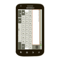
Figure 16. Burst Output Shape
¹Power Level = 0
²Set BS TCH level to -103 dBm
³Set BER TCH level to -103 dBm with 10k bits or 128 Frames
Table 5. DCS Call Parameters
¹Power Level = 0
²Set BS TCH level to -104 dBm
³Set BER TCH level to -104 dBm with 10k bits or 128 Frames
Table 6. PCS Call Parameters
Burst Output Shape should fall within the standard lim-
its of the Power Ramp.
BER measurements is only required if RX Quality reads
a value of 4 or greater.
It is recommended that handover procedures be per-
formed as shown in the following table.
Table 7. GSM/DCS/PCS Handover
GSM/DCS/PCS Call Processing
 Loading...