Troubleshooting Tables: List of Board and IC Signals 7-49
sb2 Side button #2 N5 0=Pressed Input Pul-
lup
Input Pul-
lup
sb1 Side button #1 M5 0=Pressed Input Pul-
lup
Input Pul-
lup
monitor Monitor button P11 0=Pressed Input Pul-
lup
Input Pul-
lup
cpld_ver4 CPLD version identi-
fier bit 4
(REG) Register Register
cpld_ver3 CPLD version identi-
fier bit 3
(REG) Register Register
cpld_ver2 CPLD version identi-
fier bit 2
(REG) Register Register
cpld_ver1 CPLD version identi-
fier bit 1
(REG) Register Register
cpld_ver0 CPLD version identi-
fier bit 0
(REG) Register Register
board_id8 Controller Board ID
bit 8
H12 Input Pul-
lup
Input Pul-
lup
board_id7 Controller Board ID
bit 7
H13 Input Pul-
lup
Input Pul-
lup
board_id6 Controller Board ID
bit 6
G13 Input Pul-
lup
Input Pul-
lup
board_id5 Controller Board ID
bit 5
F13 Input Pul-
lup
Input Pul-
lup
board_id4 Controller Board ID
bit 4
D13 Input Pul-
lup
Input Pul-
lup
board_id3 Controller Board ID
bit 3
E13 Input Pul-
lup
Input Pul-
lup
board_id2 Controller Board ID
bit 2
C14 Input Pul-
lup
Input Pul-
lup
board_id1 Controller Board ID
bit 1
D14 Input Pul-
lup
Input Pul-
lup
board_id0 Controller Board ID
bit 0
F14 Input Pul-
lup
Input Pul-
lup
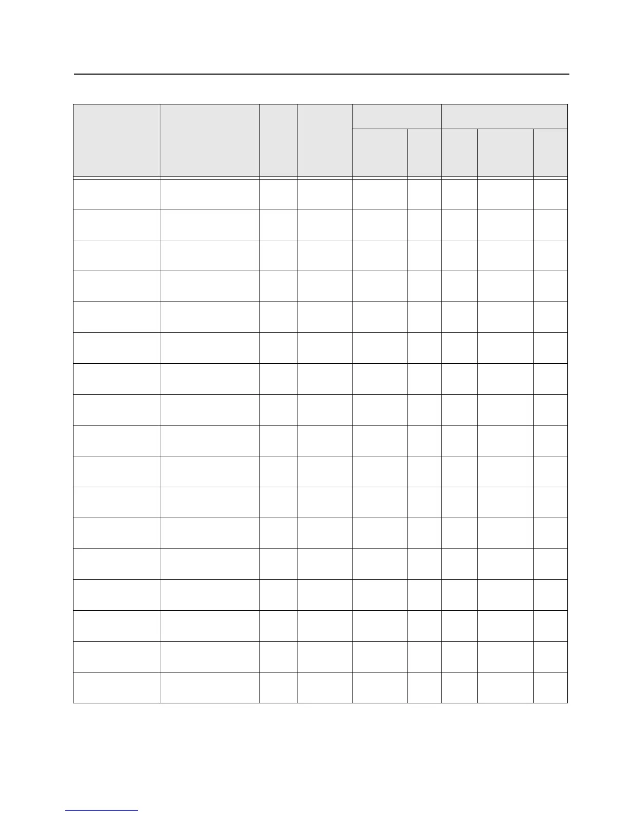
Table 7-18. Overall GPIO pin functions (Continued)
Signal Name Description
Pin
or
Ball #
Active
State
SW Initialized HW Reset
Direction
*
PU State Direction
*
PU
or
PD

 Loading...