List of Figures vii
6878215A01
List of Figures
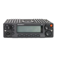
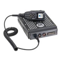
Figure 1-1. Front View of Mid Power Dash Mount Transceiver and Trunnion......................................... 1-1
Figure 1-2. Side View of Mid Power Dash Mount Transceiver and Trunnion.......................................... 1-1
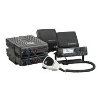
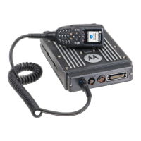
Figure 1-3. Front View of High Power (100W) Transceiver and Trunnion............................................... 1-1
Figure 1-4. Side View of High Power (100W) Transceiver and Trunnion................................................ 1-1
Figure 1-5. Front View of O3 Control Head with Coiled Cable................................................................ 1-2
Figure 1-6. Side View of O3 Control Head with Coiled Cable ................................................................. 1-2
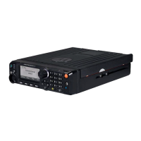
Figure 1-7. Front View of O5 Control Head with Trunnion ...................................................................... 1-2
Figure 1-8. Side View of O5 Control Head with Trunnion........................................................................ 1-2
Figure 1-9. Front View of O9 Control Head with Trunnion ...................................................................... 1-2
Figure 1-10. Side View of O9 Control Head with Trunnion........................................................................ 1-2
Figure 1-11. Top View of O9 Universal Relay Controller with Trunnion
(URC is an orderable accessory.) ......................................................................................... 1-3
Figure 1-12. Side View of O9 Universal Relay Controller with Trunnion
(URC is an orderable accessory.) ......................................................................................... 1-3
Figure 1-13. Dash Mount Configuration with O5 Control Head................................................................. 1-3
Figure 1-14. Dash Mount Configuration with Transceiver Interface Board and O3 Control Head ............ 1-4
Figure 1-15. Remote Mount Configuration with Mid Power Transceiver and O5 Control Head................ 1-5
Figure 1-16. Remote Mount Configuration with Mid Power Transceiver, Transceiver Interface Board,
and O3 Control Head............................................................................................................ 1-5
Figure 1-17. Remote Mount Configuration with High Power (100W) Radio Transceiver
and O5 Control Head............................................................................................................ 1-6
Figure 1-18. Remote Mount Configuration with High Power (100W) Radio Transceiver
and O3 Control Head............................................................................................................ 1-6
Figure 1-19. Remote Mount Configuration with Radio Transceiver and O9 Control Head ....................... 1-6
Figure 1-20. Remote Mount Configuration with Mid Power Radio Transceiver,
Universal Relay Controller and O9 Control Head (URC is optional.).................................... 1-7
Figure 1-21. Remote Mount Configuration with High Power (100W) Radio Transceiver,
Universal Relay Controller and O9 Control Head (URC is optional.).................................... 1-7
Figure 2-1. Dash Mount Radios Can Be Located in the Middle Console, on the Transmission Hump,
or Under the Dash (See Figure 2-2 for 100W Radio Install)................................................. 2-2
Figure 2-2. Remote Mount Radio Control Heads Can Be Located in the Middle Console,
on the Transmission Hump, or Under the Dash.................................................................... 2-2
Figure 2-3. Remote Mount of the Radio, O9 Control Head, and Universal Relay Controller
(URC is optional.).................................................................................................................. 2-2
Figure 2-4. Radio Installation (O5 Mid Power Dash Mount).................................................................... 2-3
Figure 2-5. Radio Installation (O3 Mid Power Dash Mount).................................................................... 2-4
Figure 2-6. Radio Installation (O5 Mid Power Remote Mount)................................................................ 2-4
Figure 2-7. Radio Installation (O3 Mid Power Remote Mount)................................................................ 2-5
Figure 2-8. Radio Installation (O3 High Power Remote Mount) .............................................................. 2-5
Figure 2-9. Radio Installation (O5 High Power Remote Mount) .............................................................. 2-6
Figure 2-10. Radio Installation of O9 Remote Mount with Transceiver (URC is optional.)........................ 2-6
Figure 2-11. Radio Installation (O9 Remote Mount with Pinouts) ............................................................. 2-7
Figure 2-12. Remote Control Head Pinouts .............................................................................................. 2-7
Figure 2-13. Cabling Interconnect Diagram for Dash Mount (Cannot Be Used for 100W Radios) ........... 2-8
Figure 2-14. Cabling Interconnect Diagram for Remote Mount................................................................. 2-9
Figure 2-15. Cabling Interconnect Diagram for 09 Remote Mount (URC is optional.) ............................ 2-10
Figure 2-16. Trunnion Orientation (Cannot Be Used for 100W Radios).................................................. 2-15
Figure 2-17. Trunnion Orientation for 100W Radios................................................................................2-15
Figure 2-18. Transmission Hump Trunnion Mounting ............................................................................. 2-16
Figure 2-19. Below Dash Trunnion Mounting.......................................................................................... 2-17
 Loading...