Signal
Minimum Devia-
tion
Nominal Devia-
tion
Maximum Devia-
tion
GNSS test pattern - simulcast undetermined 3.00 kHz undetermined
ASTRO
®
25 system voice 3.24 kHz 3.60 kHz 3.96 kHz
ASTRO
®
25 system wide pulse undetermined 3.00 kHz undetermined
5.11.2
Monitoring the Power Supply Module
Perform the following procedure to monitor the power supply.
Procedure:
1 Connect to the base radio
in Configuration/Service Software (CSS) through an Ethernet
connection. See Connecting Through an Ethernet Port Link on page 140.
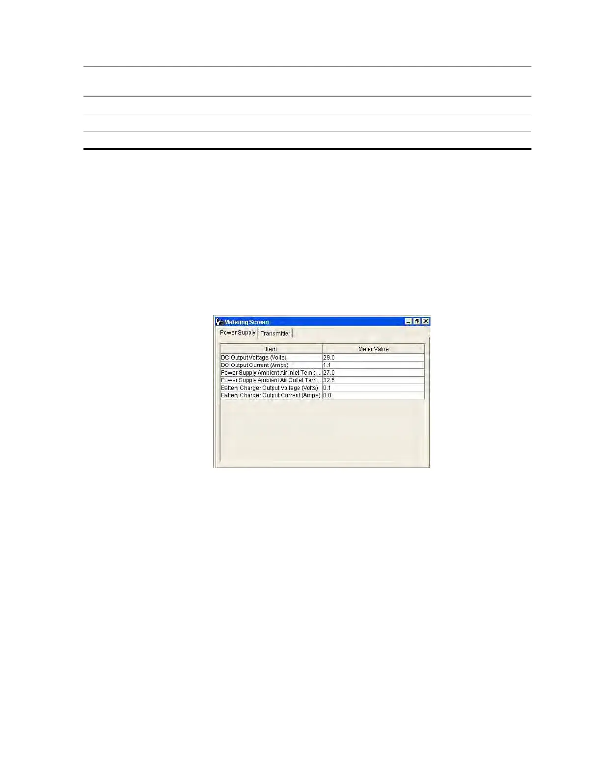
2 From the menu, select Service → Metering Screens.
The Metering Screen window opens on the Power Supply tab.
Figure 79: Metering Screen Window
5.11.3
Verifying Receiver Performance for FDMA Operation
When and where to use:
Use this procedure to verify receiver performance by measuring the Bit Error Rate (BER) and Received
Signal Strength Indication (RSSI) for digital operation.
Procedure:
1 Make the following connections to the base radio:
a Disconnect the BNC antenna cable (or N connector if preselector is present) from the receive
antenna Port.
b Connect the service monitor GEN port to the base radio Antenna Port.
2 Set up the service monitor:
a Set modulation to Project 25 (C4FM) with a Standard 1011 test pattern.
b Set the service analyzer to generate at the receive frequency.
c Set the RF level an initial value of -47 dBm.
MN003286A01-E
Chapter 5: GTR 8000 Base Radio Optimization
185

 Loading...


