MN003109A01_aa
1-6 Introduction Standard Configurations
1.2 Standard Configurations
1.2.1 Dash Mount Configuration - Mid Power
NOTE: The dash mount configuration is not applicable for O9 control heads.
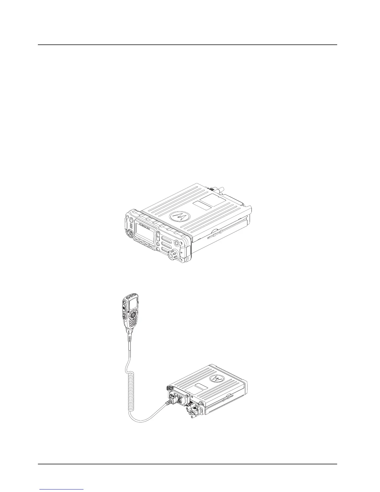
There are two versions of the APX mobile dash mount. The first are the O2, O5 and O7 control
heads which are mounted on the front of the transceiver housing. The second is the O3 control head
which is connected to the transceiver through a coiled cable, which is plugged into the CAN
connector on the transceiver.
Electrical connection between the two takes place within the radio through a flexible circuit board
between the connectors on the front of the transceiver and at the back of the control head for O2, O5
and O7.
Figure 1-24. Dash Mount Configuration for O2 Control Head
Figure 1-25. Dash Mount Configuration for O3 Control Head
(No Extension Cable Present)
Draft

 Loading...


