MN003109A01_aa
Standard Configurations Planning the Installation 2-17
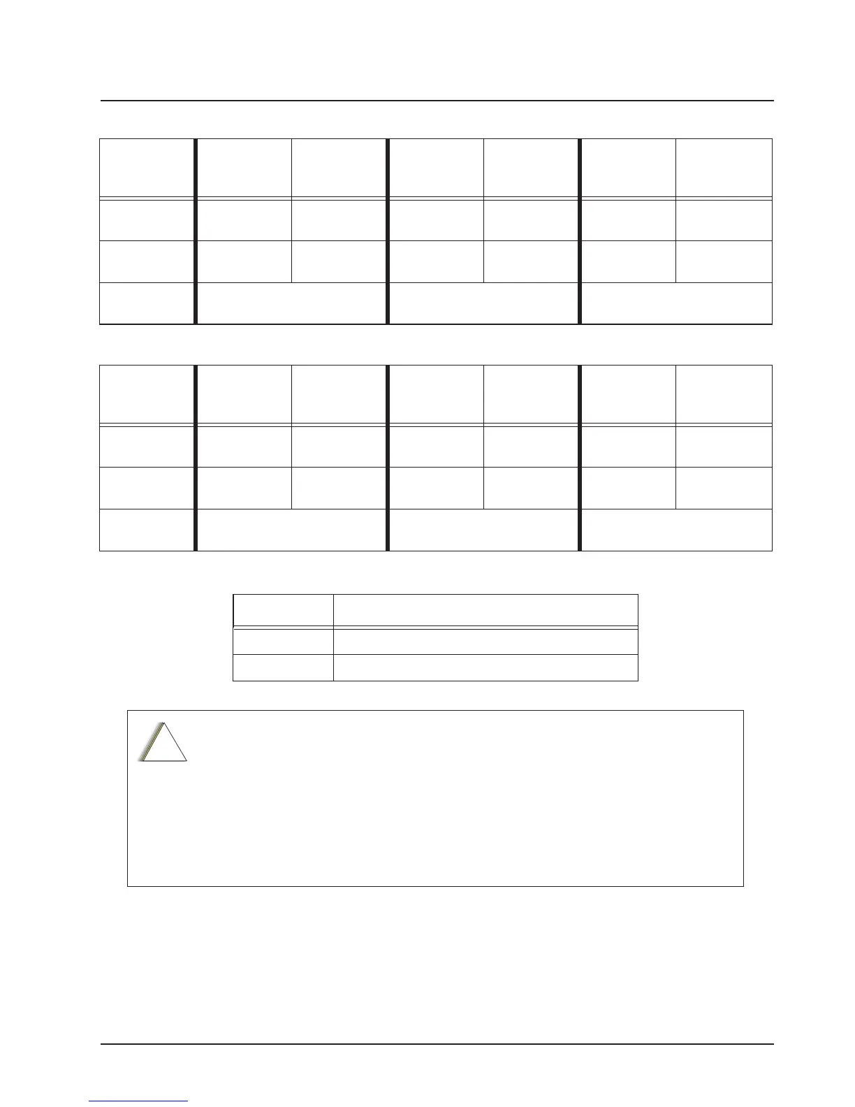
Table 2-1. Dash and Remote O2, O3, O5, O7 or O9 Radio Power ON @ J2
Dash/Remote
Mount
Transceiver
Red Power
Wire
HLN6863
Thin Red Wire
@ J2
Transceiver
Red Power
Wire
HLN6863
Thin Red Wire
@ J2
Transceiver
Red Power
Wire
HLN6863
Thin Red Wire
@ J2
Connected to
battery
XXX X
Connected to
ignition switch
XXX
Ignition switch
controls
No ignition switch control. Enables ignition switch functionality
as programmed in the codeplug.
Illegal wiring configuration. See
CAUTION note.
Table 2-2. Remote O2, O5, O7 or O9 Radio Power ON @ J200
Remote
Control Head
Red Wire
@J200
Control Head
Yellow Wire
@J200
Control Head
Red Wire
@J200
Control Head
Yellow Wire
@J200
Control Head
Red Wire
@J200
Control Head
Yellow Wire
@J200
Connected to
battery
XXX X
Connected to
ignition switch
XXX
Ignition switch
controls
No ignition switch control. Enables ignition switch functionality
as programmed in the codeplug.
Illegal wiring configuration. See
CAUTION note.
Table 2-3. Ignition Interface Cables
Part Number Description
HLN6863_ Cable, M.A.P. 26pin with Only Ignition and SPK
KT000274A01 Y-Cable, M.A.P to M.A.P. and DB 25
DO NOT connect any wires to the battery terminals until you have finished the entire
radio installation (Dash or Remote Mount) configuration to avoid potential equipment
damage.
Incorrect wiring of the radio may result in incorrect ignition sense detection, incorrect
power-on state, or incorrect power-off state of the radio system.
The Control Head Power cable wire (RED) and Transceiver Power cable wire (RED)
are always attached to the battery terminal and NOT to the ignition switch.
Draft

 Loading...


