MN003109A01_aa
2-28 Standard Configurations Radio Mounting
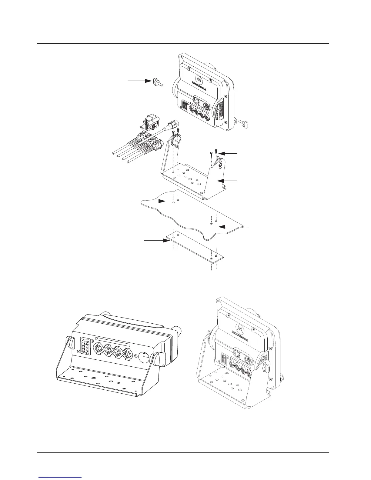
Figure 2-30. O9 Control Head Installation Exploded View
Figure 2-31. O5 and O9 Control Head Rear View
Adjust the control head to desired
angle and secure with wing screws
Use four mounting screws on all
installations
Trunnion
Drill four 5/32” holes in
mounting surface
Mounting surface
IMPORTANT:
Use a metal backing plate (not
supplied) if mounting trunnion on
plastic or unstable surface
Draft

 Loading...


